
Nodular cast iron belongs to a typical paste solidification mode. The possibility of shrinkage porosity, shrinkage cavity, air hole, slag inclusion, insufficient pouring and other defects in the pouring process is much higher than that of other types of cast iron such as gray cast iron. Therefore, in the production and pouring process of nodular cast iron, the mold filling must be stable. If turbulence occurs due to too fast mold filling speed, it may not only be involved in gas to form subcutaneous pore defects, but also slag inclusion defects may occur when the sand mold strength is insufficient. In this section, magma software is used to simulate the filling process of automobile hub support, and OpenGL technology can be used to dynamically observe the velocity field, temperature field and pressure field in this process. Fig. 1 is the velocity distribution diagram corresponding to different times (30%, 50%, 80%, 100%) during liquid metal filling. The speed bar on the right side of the figure shows the speed difference in different colors, and the filling speed gradually increases from bottom to top.
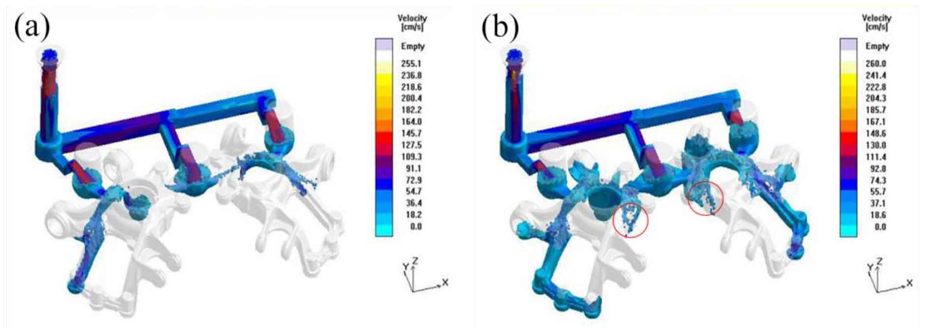
It can be seen from the flow of liquid metal in the figure that during pouring, the liquid metal first enters the transverse sprue through the sprue cup and sprue, then flows into the inner sprue and riser, and finally flows into the ductile iron cavity through the riser neck. After 8 s, the mold filling process is completed. It can be seen from Figure 1 (a) that the maximum flow rate of liquid metal from the runner to the ingate at the initial stage of mold filling is about 73 cm / s, but when the liquid metal enters the riser from the ingate, the speed suddenly increases to 127.5 cm / s, and then the flow rate decreases and flows into the mold smoothly, indicating that the riser is set between the ingate and nodular cast iron, which effectively prevents the liquid flow from directly rushing into the mold at a faster speed, This leads to sand mold damage and defects. When the mold filling is up to 50%, as shown in Fig. 1 (b), the filling process of nodular cast iron for left and right hub supports is basically synchronized. However, due to the height drop in the structure of nodular cast iron, there is liquid flow splash at the local position of the red circle in the figure, which may lead to gas entrainment. Moreover, due to the uneven impact of the alloy liquid, the uneven strength of the core after heating may lead to sand particles involved in the fluid, resulting in slag inclusion defects. When the mold filling reaches 80% (Fig. 1 (c)), the liquid metal rises steadily in the mold, and the phenomena of local splash and erosion disappear. Only some liquid flow intersections have a slightly faster mold filling speed. When the mold filling time reaches 8 s (Fig. 1 (d)), the mold filling is completed, the mold cavity is completely filled, and there is no phenomenon of insufficient pouring.
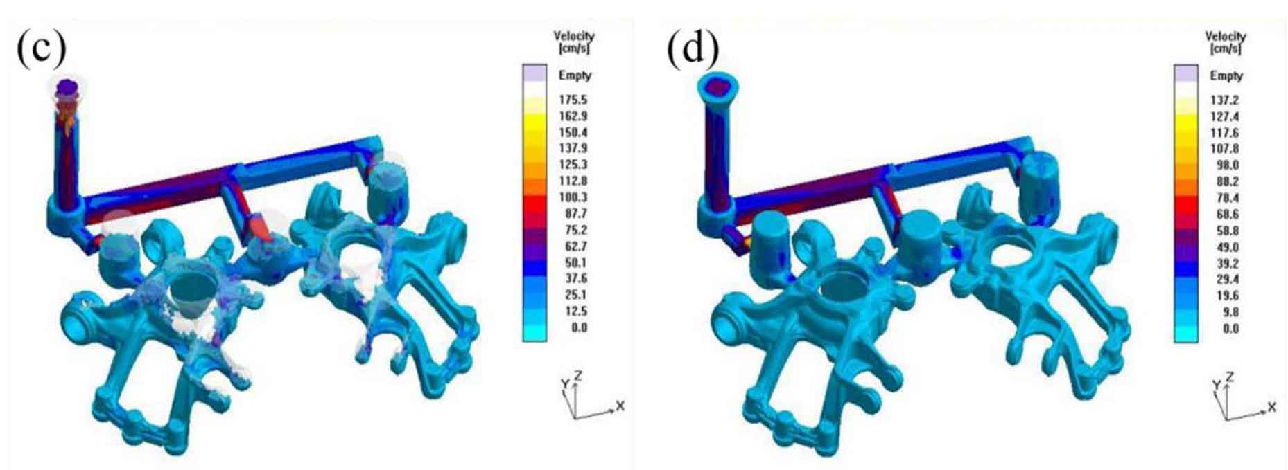
Figure 2 shows the temperature field distribution in the mold at different times of mold filling. The temperature scale is on the right, and yellow represents the highest temperature part, which is 1370 ℃; Blue indicates the part with the lowest temperature, which is 1170 ℃. According to Fig. 2 (a) and Fig. 2 (b), it can be seen that when the nodular cast iron of the hub support is not more than half filled, the temperature difference of the molten metal in the mold is small, and the overall temperature difference does not exceed 15 ℃, indicating that there is little heat loss of the molten metal in the early and middle stages of filling. At the later stage of mold filling, the temperature of molten metal in the mold began to show obvious differences, as shown in Fig. 2 (c) and Fig. 2 (d). This is because the volume of nodular cast iron is large, and there is a gap in the filling time of each part. Therefore, the temperature difference between the outer bushing and the connecting hole of the upper control arm filled earlier and the last filled area is large. At the same time, the temperature of the thinnest part of the cast iron decreases rapidly, and the temperature of the thinnest part of the cast iron ball does not decrease at the same time. However, when the mold filling is completed, the minimum temperature in the whole mold is 1166 ℃ higher than the solidus temperature of the material, and there will be no defects such as insufficient pouring, so the temperature field distribution in the mold filling process is reasonable.
The pressure field distribution in the mold filling process simulated under the initial casting process scheme of the casting is shown in Figure 3.
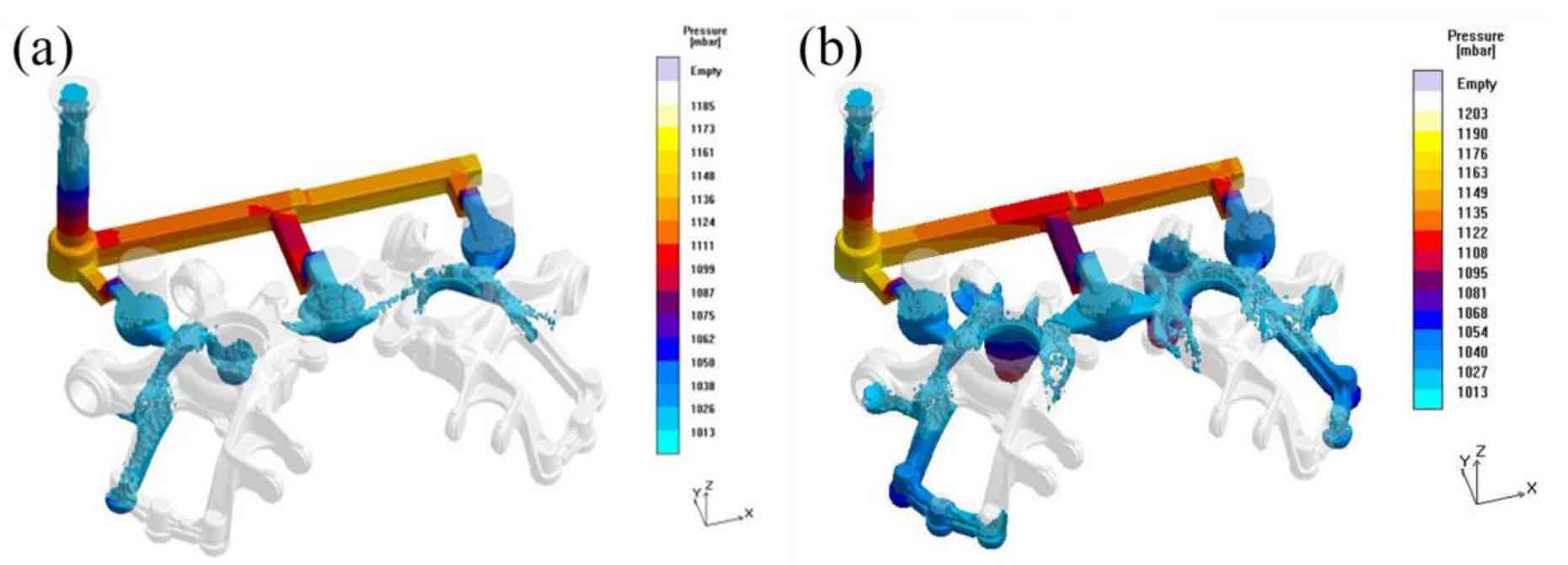
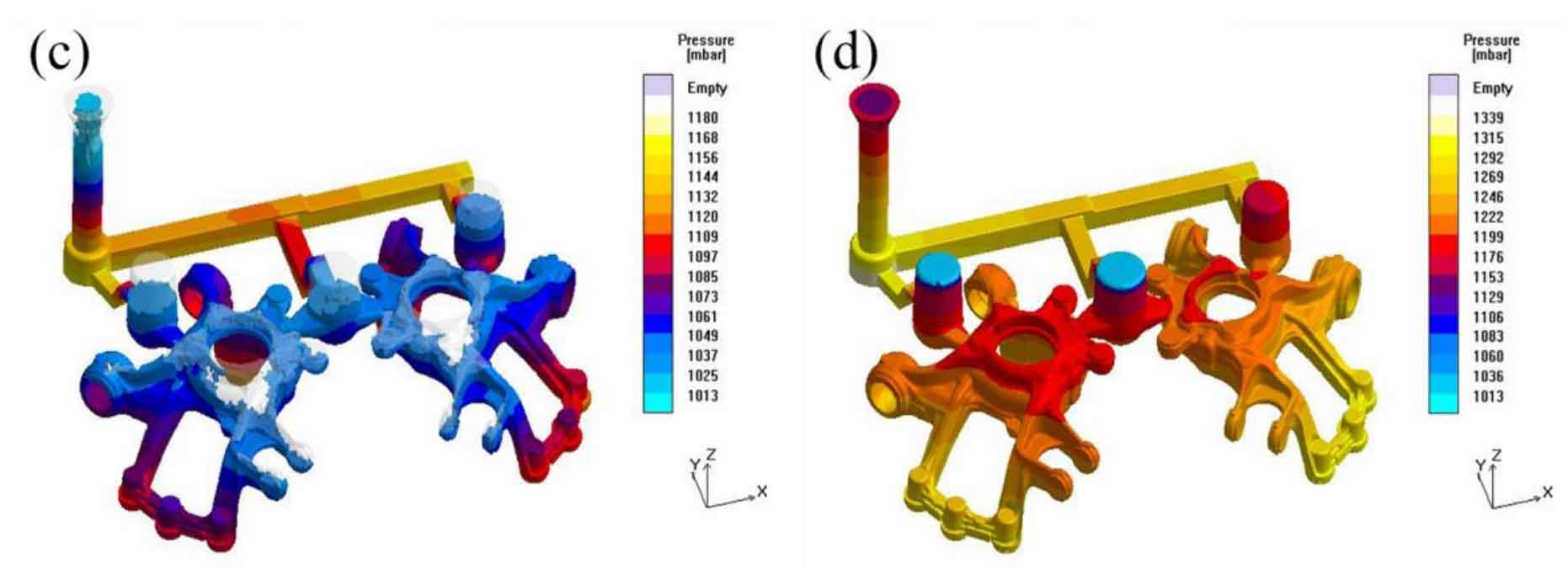
As can be seen from Figure 3 (a), when the filling rate is 30%, the liquid metal has flowed into the mold, and the pressure at the front end of the liquid flow is about 1026 mbar. The liquid flow pressure distribution in the mold is relatively uniform. The lower filling pressure can ensure the filling capacity and reduce the impact on the mold at the same time. With the progress of mold filling process, when the mold filling rate is 50% (Fig. 3 (b)), the overall pressure in the mold is still evenly maintained at a low level. However, when the mold filling rate increases to 80%, with the filling of most parts of the casting, the pressure difference in the mold becomes obvious along the z-axis, but the pressure difference is small, about 1.1 times. Until the mold filling of the casting is completed (Fig. 3 (c) and (d)), the pressure difference in the mold does not exceed 1.5 times, indicating that the selection of parting surface and pouring position in the process scheme is reasonable, and the overall pressure difference in the mold filling process is small, which is conducive to preventing sand inclusion and other defects.