
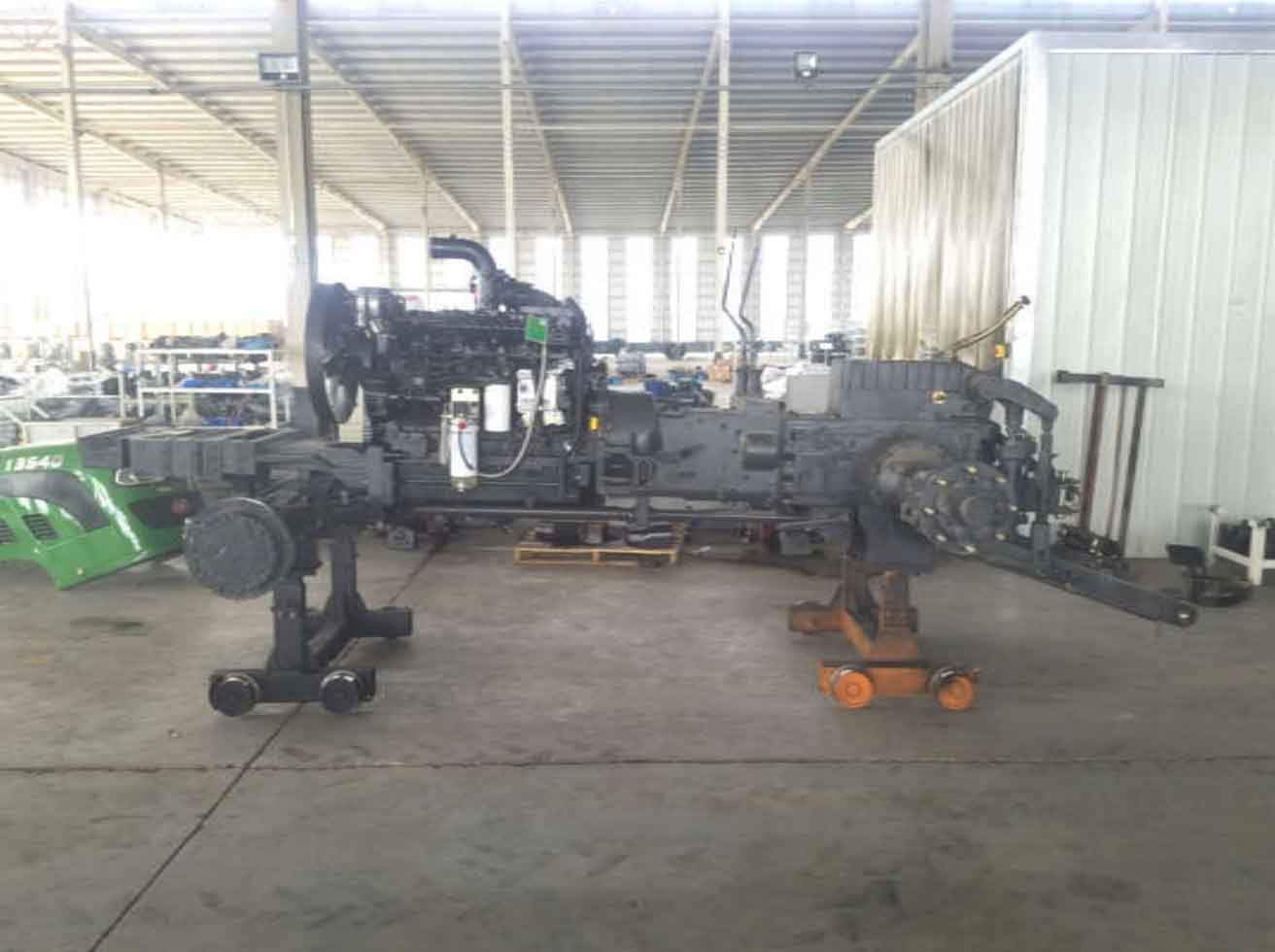
Through the actual observation of the assembly and connection relationship of tractor castings, we can know that the engine, gearbox and rear axle are directly connected through bolts, and there is no special frame to carry these weights, so the gravity generated by the castings in the front of these tractors will also act on the gearbox, as shown in Figure 1.
Through the actual measurement of the position and size of each casting, draw the layout diagram of each casting with AutoCAD 2.
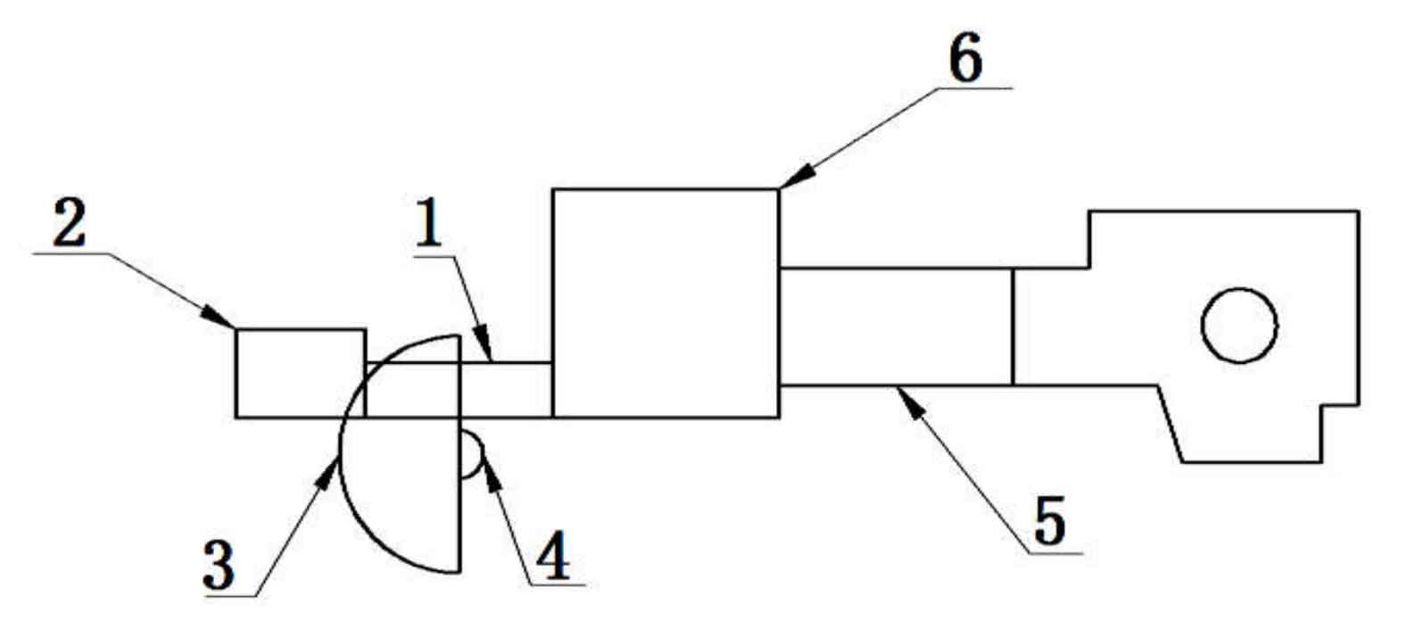
4 – front suspension 5 – transmission 6 – engine
Measure the weight of each casting, as shown in the table.
| Serial number | Name | Mass (kg) |
| 1 | Front counterweight frame | 116 |
| 2 | Front counterweight | 416 |
| 3 | Front tires (two) | 162 |
| 4 | Front suspension | 298 |
| 5 | Transmission case | 235 |
| 6 | Engine | 760 |
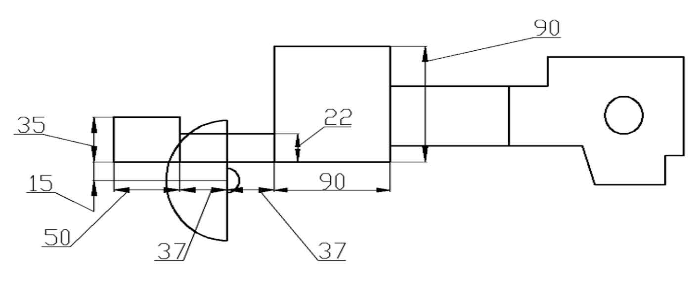
The relative installation position between castings is obtained by actual measurement, as shown in Figure 3.
Because castings 1, 2, 3, 4 and 6 are simple geometric objects, their center of gravity position is at the centroid position, and the mass is gathered into particles to the centroid position of each casting. A rectangular coordinate system is established with the lower left point of Casting 2 as the coordinate origin. The point is the center of gravity coordinate of the front counterweight, B is the center of gravity coordinate of the front counterweight bracket and the center of gravity of the front suspension, and D is the center of gravity coordinate of the engine. The total weight of the front counterweight engine is 1752kg.
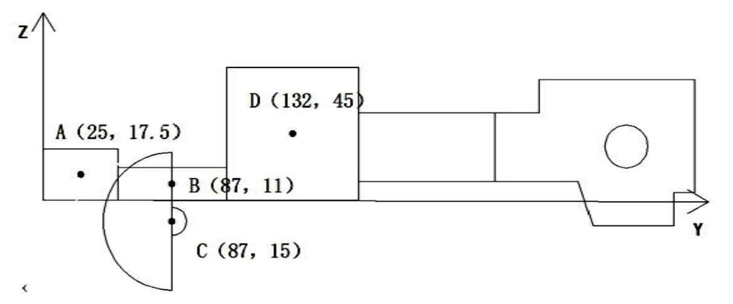
The formula for solving the center of gravity position of multi casting assembly is as follows:
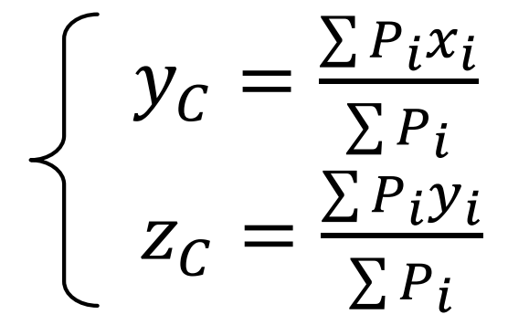
Bring the data in table and Figure 4 into the formula to calculate the center of gravity position of the combined casting:
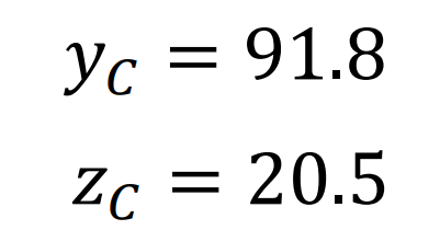
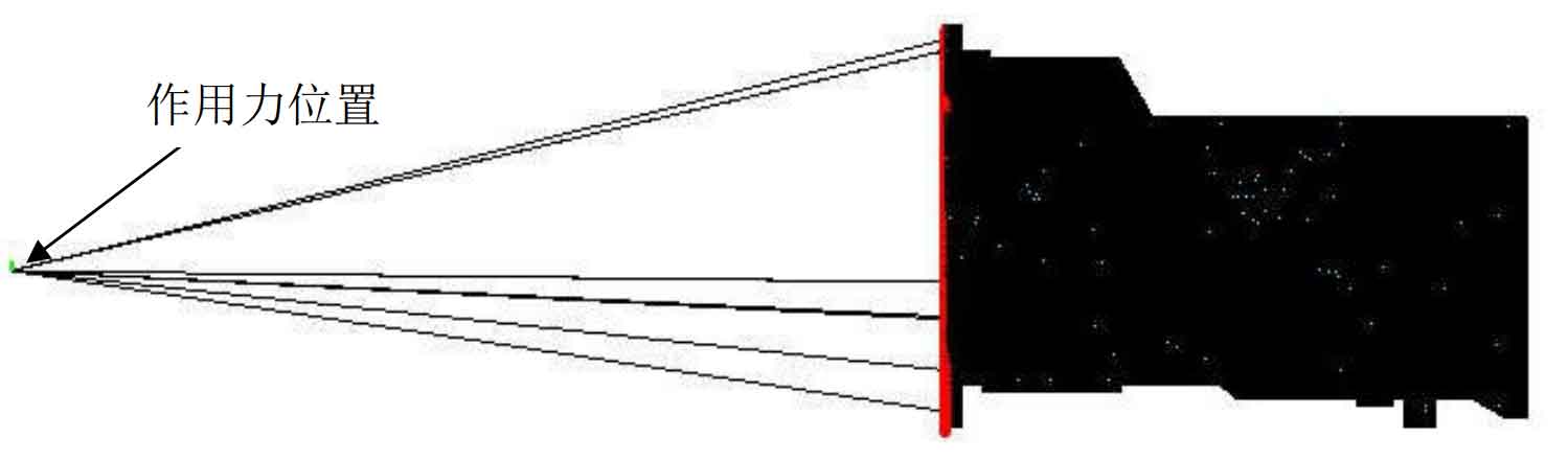
The tractor is basically symmetrical left and right, and the default center of gravity is in the YZ plane, so determine the force of the gravity coordinate point on the gearbox housing at the position of (0,91.8,20.5). The coordinates are converted into HyperMesh through the coordinate system. The coordinates of the action point are (1262, 0, – 805), and the position of the action point is shown in Figure 5.