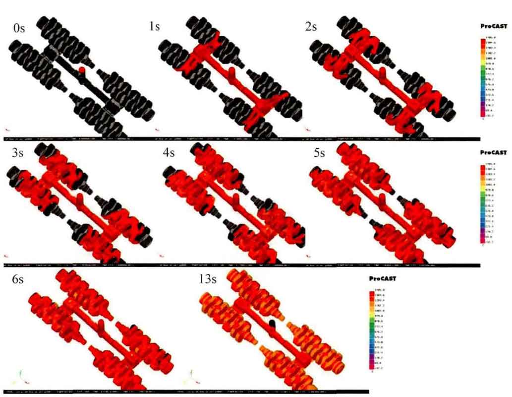
ProCAST calculates the flow field, as shown in Figure 1. It can be seen that the mold filling speed is very fast at the beginning. At 1s, the molten metal begins to fill the gating system and flow to the crankshaft casting. The flow speed in the crankshaft casting is slow. It reaches both ends of the crankshaft casting in about 5S, and the mold filling is complete after 13s. In the whole filling process, the temperature also changed, which began to decrease from 1420 ° C at the beginning. When filled, the edge part has basically reached 1200 ° C, that is, it has begun to enter the solidification process.
Then, the filling calculation is completed, and the solidification process is shown in Figure 2.
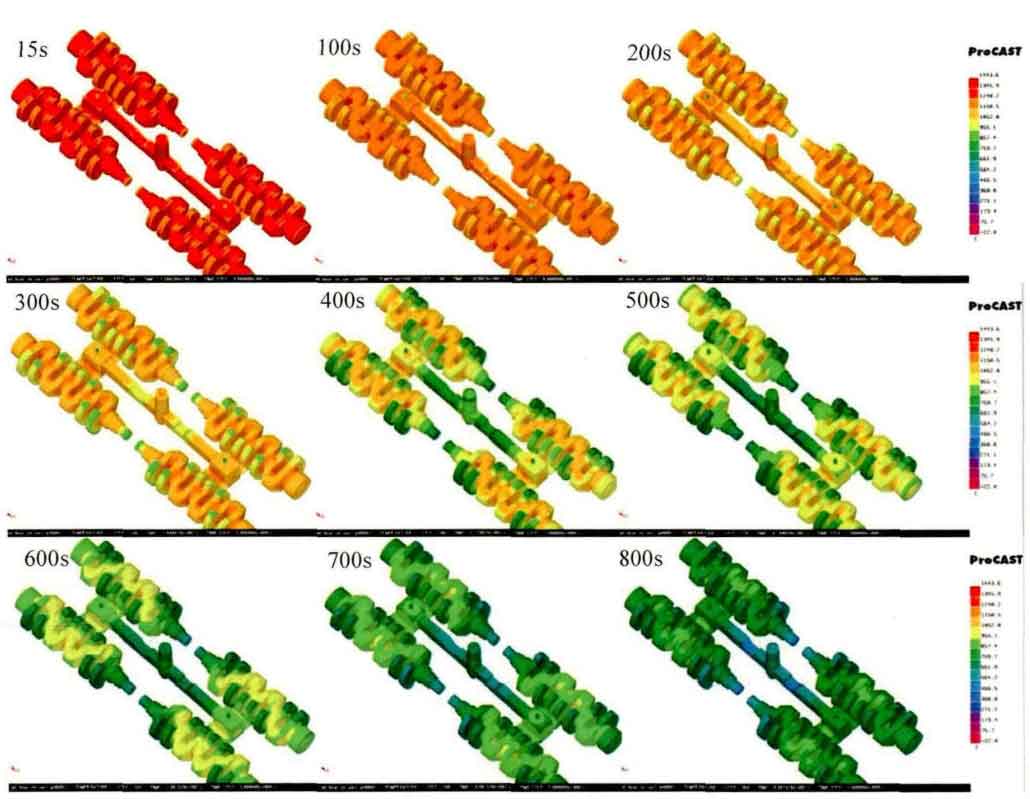
The casting has basically entered the solidification stage at 15s. At 800s, most of the temperature of the crankshaft casting has been reduced to the range of 600-700 ° C, and the core is about 1000 ° C. It can be seen from Fig. 3 that the temperature drop of the crank edge of the crankshaft casting, the smaller end of the crankshaft casting and the sparing injection system is the fastest, about 200 ° C lower than the middle part of the crankshaft casting and about 400 ° C lower than the most central part.
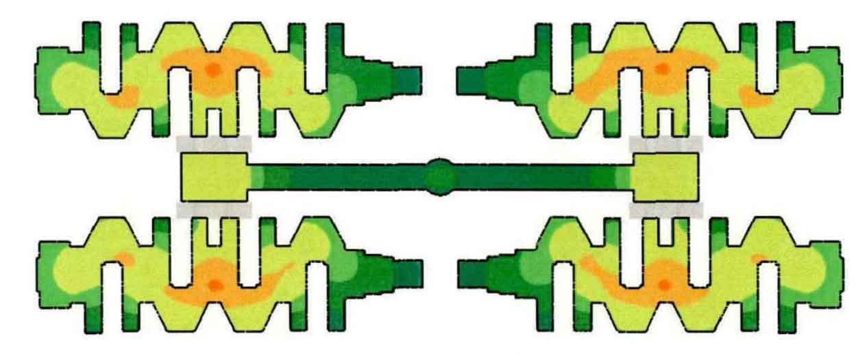
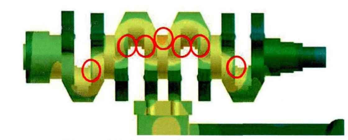
Take a quarter of the crankshaft casting for observation, as shown in Figure 4. The edge of the crank and both ends of the crankshaft are cooled first, and the cooling speed is the fastest in the thinner and thinner places; The temperature of the shaft center of the crankshaft casting is high; The temperature at the hot spot is the highest at the same time. From the distribution of temperature field, it can be inferred that the edge of crankshaft casting is solidified first, and the core and hot spot are solidified finally. Therefore, it is also the most difficult to get feeding, which is easy to produce casting defects such as shrinkage porosity and shrinkage cavity.
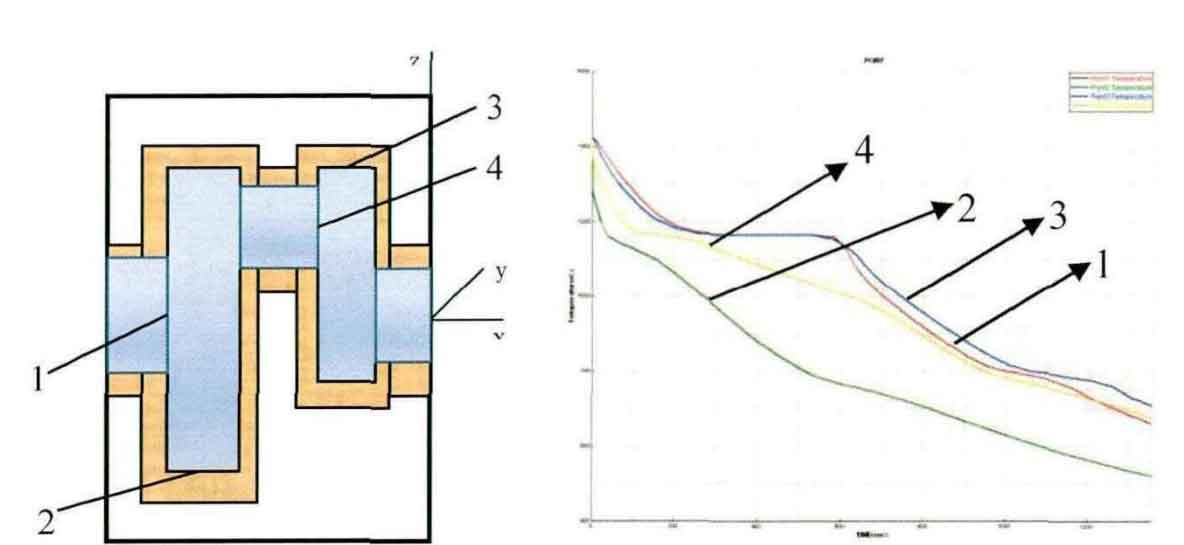
In order to study the cooling rate of different parts of crankshaft during casting, several special nodes were selected and their cooling curves were studied. Node 1 is located in the center of the main shaft and node 4 is located in the center of the connecting rod journal. The two points are at the hot joint, and the cooling speed is the slowest; Node 2 is located at the lowest end of the large sector, and its cooling speed is the fastest from the temperature field simulation; Point 3 is at the top of the small sector. Figure 5 shows the cooling curve of these points. From the curve, it can be seen that the solidification process is gradual solidification from the outer surface of the crankshaft to the center, and the cooling rate is similar.