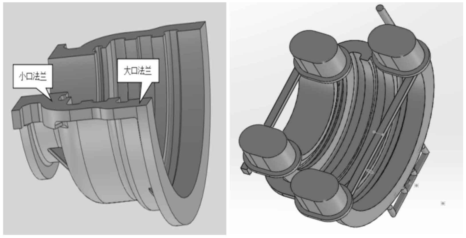
The upper half of the middle cylinder block for a certain type of steam turbine is made of ZG20CrMo, the gross weight of the casting is 6400 kg, and the process yield is 55%. The main structure is composed of cylinder wall with equal wall thickness of 45 mm plus horizontal flange and vertical flange. The thickness of small port flange is 160 mm and the thickness of large port flange is 95 mm. It is a typical structural member with thin and thick walls (Fig. 1a). Cold hardening furan resin sand molding, electric arc furnace smelting and bottom pouring process are adopted (Fig. 1b).
1. Calculation of split modulus of cylinder block
1.1 Split hot joint
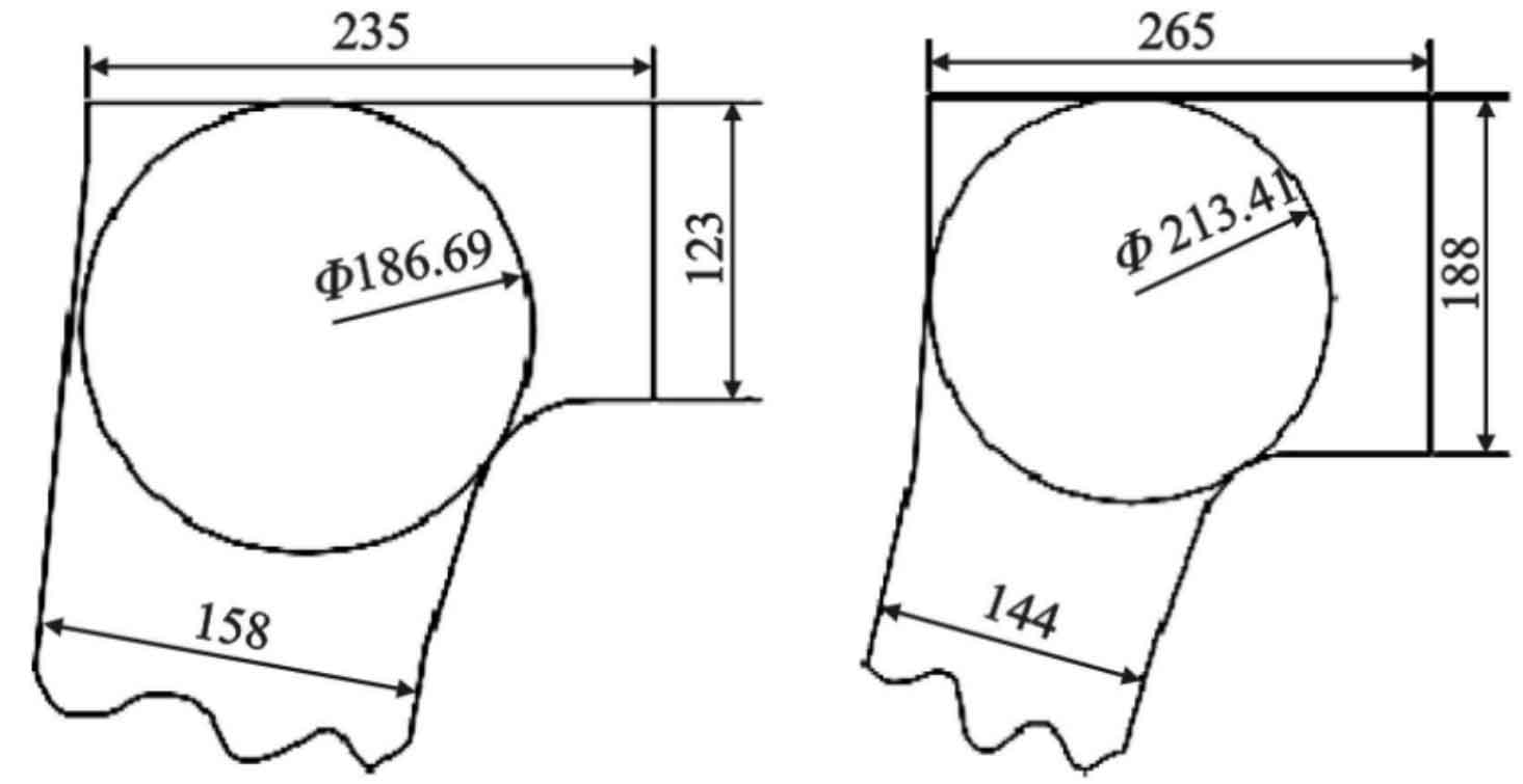
The flange at the split of the middle steam cylinder block intersects with the wall thickness of the cylinder block, draw the graph at the intersection node, and make the inscribed circle at the intersection node, which is the hot spot circle of the cylinder block. The main wall thickness of the cylinder block is 45 mm, the thickness of the small flange is 160 mm, the thickness of the large flange is 95 mm, the machining allowance of the designed split is 25 mm, and the process correction amount of the back of the flange is 3 mm. See Fig. 2 for the hot pitch circle at the 95mm thick part of the large mouth flange and 160mm thick part of the small mouth flange.
1.2 Calculation of modulus
Any complex casting can be regarded as a combination of many simple geometric bodies (plates, rods, cylinders, etc.). The modulus of the casting can be calculated simply by the method of geometric approximation.
The split flange of the middle steam cylinder can be regarded as a rectangular rod, and the modulus at the hot joint of the large and small flange shall be calculated according to the Formula M = V / A. Modulus at large flange M = 6.4 cm; Modulus at small flange M = 6.95 cm.
2. Design of split riser of cylinder block
Observe the basic conditions of sequential solidification. In the process of feeding the casting from the riser, the metal in the riser is gradually reduced, and the shrinkage cavity is formed on the top surface to increase the heat dissipation surface area. Therefore, the riser modulus is continuously reduced, and the casting modulus is supplemented by hot liquid metal. The relative reduction of riser modulus is about 17% of the original modulus, so a safety factor is generally set for the riser, and the safety factor of steam cylinder riser is 1.2 [1]. Feeding efficiency of waist cylindrical riser η Take 12%.
2.1 Riser design at large flange
Modulus m large mouth = 6.4 × 1.2=7.68; Design riser size: y475 × five hundred and seventy-five × 400; Riser weight = 700 kg.
2.2 Riser design at small flange
Modulus m small port = 6.95 × 1.2=8.34; Design riser size: y475 × six hundred and seventy-five × 400; Riser weight = 850 kg.
3. Layout of split riser
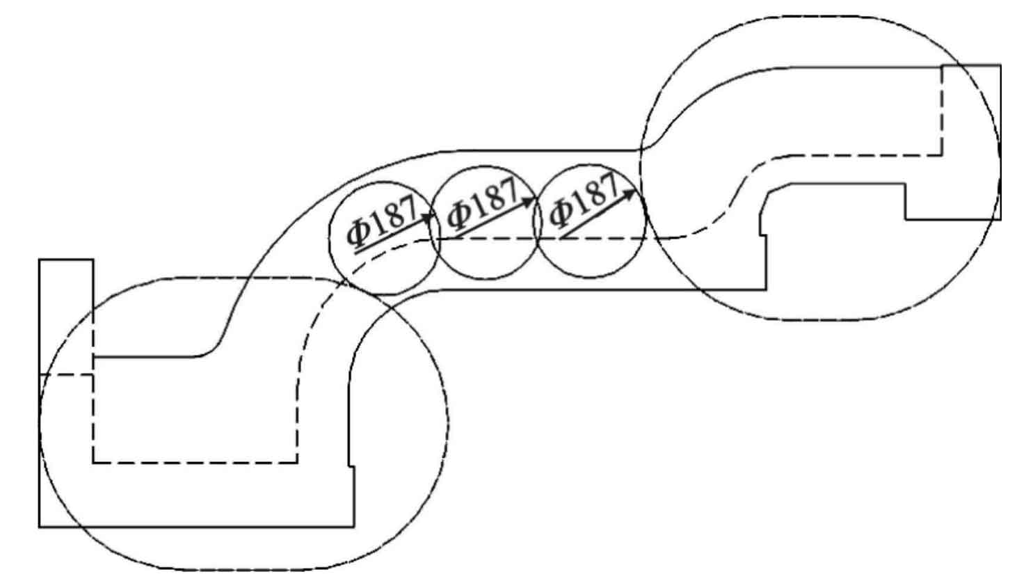
The riser layout is shown in Figure 3. The selection of riser position covers all the hot joints at both ends of the split, and the distance between risers is less than 3 times of the minimum hot joint at the flange of the split. Within the effective feeding range of the riser, the design process of the riser can be calculated theoretically, and the full feeding in the vertical and horizontal directions of the flange surface of the middle cylinder block can be realized at the same time.
4. Numerical simulation results
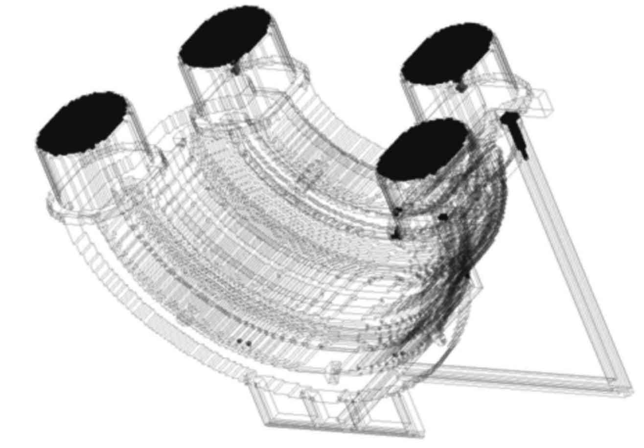
The numerical simulation can accurately judge the loose defects of the casting. From the simulation results (Fig. 4), the setting of the split riser of the middle steam cylinder block casting is reasonable, there are no defects between the risers, and the overall scheme of the casting process is feasible.
5. Actual test results
The casting flange split produced by this process scheme shall be processed according to JB / t9630 2. According to the standard flaw detection, excessive defects were found in the middle layer of the flange between risers. The defective parts were removed by arc gouging and polished for penetration flaw detection. There were loose defects with a defect area of about 150 mm × 100 mm。 The test results show that the dense structure can not be obtained between the split flange risers of the actual production steam cylinder block. The main reason may be that the temperature distribution in the center of the flange between risers is relatively flat due to the influence of riser heat. Within a certain period of solidification, the center of the flange tends to solidify in paste, resulting in loose structure.


