
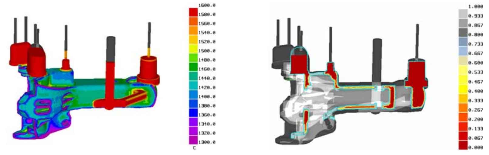
Longitudinal section distribution of independent liquid phase zone in the original casting process of hook body
Figure 1 shows the temperature distribution results of the hook body 5 s after it starts to solidify. The solidification sequence is from the lower part of the hook head to the upper part and the hook tail. Figure 3-8 shows the feeding effect of the riser observed through the longitudinal section distribution of the independent liquid phase area during the solidification of the hook body. As can be seen from Figure 2, the feeding channel at the riser is relatively unobstructed. Figure 3 shows the location of the hot spot predicted by the independent liquid phase region. It can be seen from Figure 3 that the structure of the hook head is complex, the wall thickness is uneven, and the cooling shrinkage is inconsistent. There are independent liquid phase areas at the inner and outer corners of the hook head, the root of the traction table in the hook cavity, and the junction corner between the hook head and the hook body. It is difficult to feed the riser. These parts are very easy to form hot joints, resulting in shrinkage porosity, shrinkage cavity and hot crack. Figure 4 shows the prediction of shrinkage porosity defects. The shrinkage porosity model in ProCAST is used to predict shrinkage porosity defects. The red area in the figure is the location where shrinkage porosity may occur. It can be seen from Figure 4 that shrinkage porosity mainly occurs at the junction corner between the hook head and the hook body, the inner and outer corners of the hook head, the root of the traction table in the hook cavity, etc. the structure of the hook head is complex, the wall thickness is uneven, and the cooling shrinkage is inconsistent. It is normal to produce a certain amount of shrinkage porosity, and the effect of joint feeding is general.
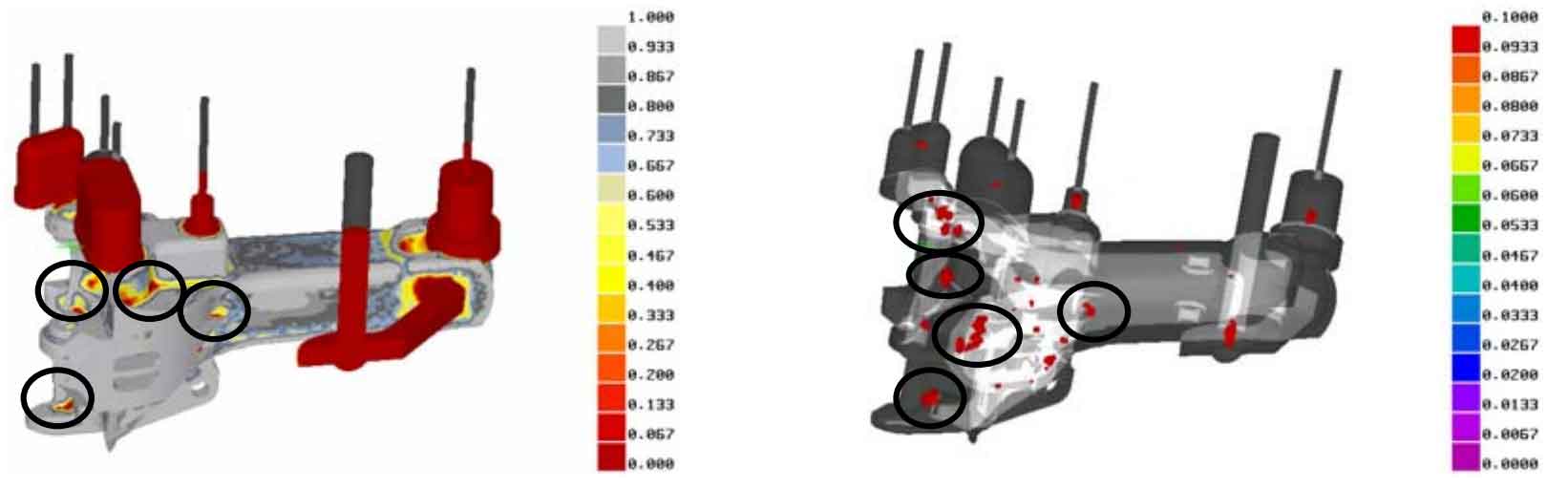
Prediction of shrinkage porosity in original casting process of hook body
Fig. 5 and Fig. 6 are the simulation results of stress field in the solidification process of hook body. Figure 5 shows the effective stress distribution. It can be seen from Figure 5 that the parts with large equivalent stress are mainly the riser root, most of the parts around the coupler tail pin hole, the corners between the hook body and the coupler head and the corners of the complex surface inside the coupler head. These parts are very sensitive, with high stress level and large final residual stress. If they are not handled properly in the processing processes such as handling, riser cutting and post-treatment, they are likely to cause cracks. Figure 6 shows the prediction results of hot cracking tendency. It can be seen from Figure 6 that the possible parts of hot crack are basically consistent with the parts with large equivalent stress mentioned above, especially at the transition corner between hook body and hook head and at the root of pouring riser. The improvement measures that can be taken are to increase the fillet radius of riser, ingate root and key corners on the basis of ensuring the dimensional accuracy of parts, and further improve the layout of cold iron.
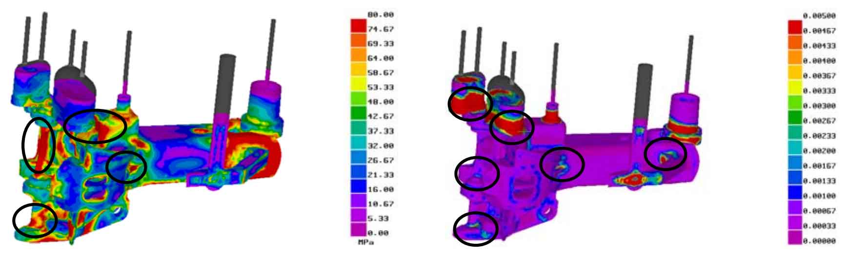
Prediction of hot crack in original casting process of hook body