
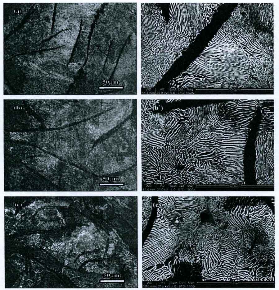
The figure shows the matrix structure of gray cast iron with different wall thickness. Among them, figures (a) and (a’), (b) and (b’), (c) and (C’) are the matrix structure in gray cast iron with wall thickness of 20mm, 40mm and 60mm respectively.
During eutectoid transformation, primary austenite generates ferrite, ferrite + pearlite, or pearlite, which mainly depends on the carbon content of austenite.
① When the carbon content of primary austenite is very low, gray cast iron with ferrite matrix will be formed;
② When the carbon content of primary austenite is less than 0.5%, the dendrite of primary austenite will change into a mixed structure of ferrite and pearlite;
③ When the carbon content of primary austenite is about 0.5%, the primary austenite is completely transformed into pearlite, forming pearlite matrix gray cast iron.
It can be seen from the figure that the matrix structure of gray cast iron with different wall thickness is pearlite, which is caused by the high carbon content in primary austenite.
Comparing the flake spacing of pearlite, it can be seen that the flake spacing of pearlite in gray cast iron increases with the increase of sample wall thickness, especially in the sample with wall thickness of 60mm. This is because the larger the wall thickness of the sample, the longer the solidification time of the metal solution and the solid-state phase transformation time after solidification, the stronger the diffusion ability of the carbon atoms, and the longer the diffusion time, so the farther the diffusion distance of the carbon atoms, and finally the pearlite with large sheet spacing is generated. As the diffusion time of carbon atoms is prolonged, the carbon atoms in pearlite are fully diffused to the cementite sheet, resulting in the formation of large thickness sheet cementite in the pearlite of gray cast iron.