
1. Causes
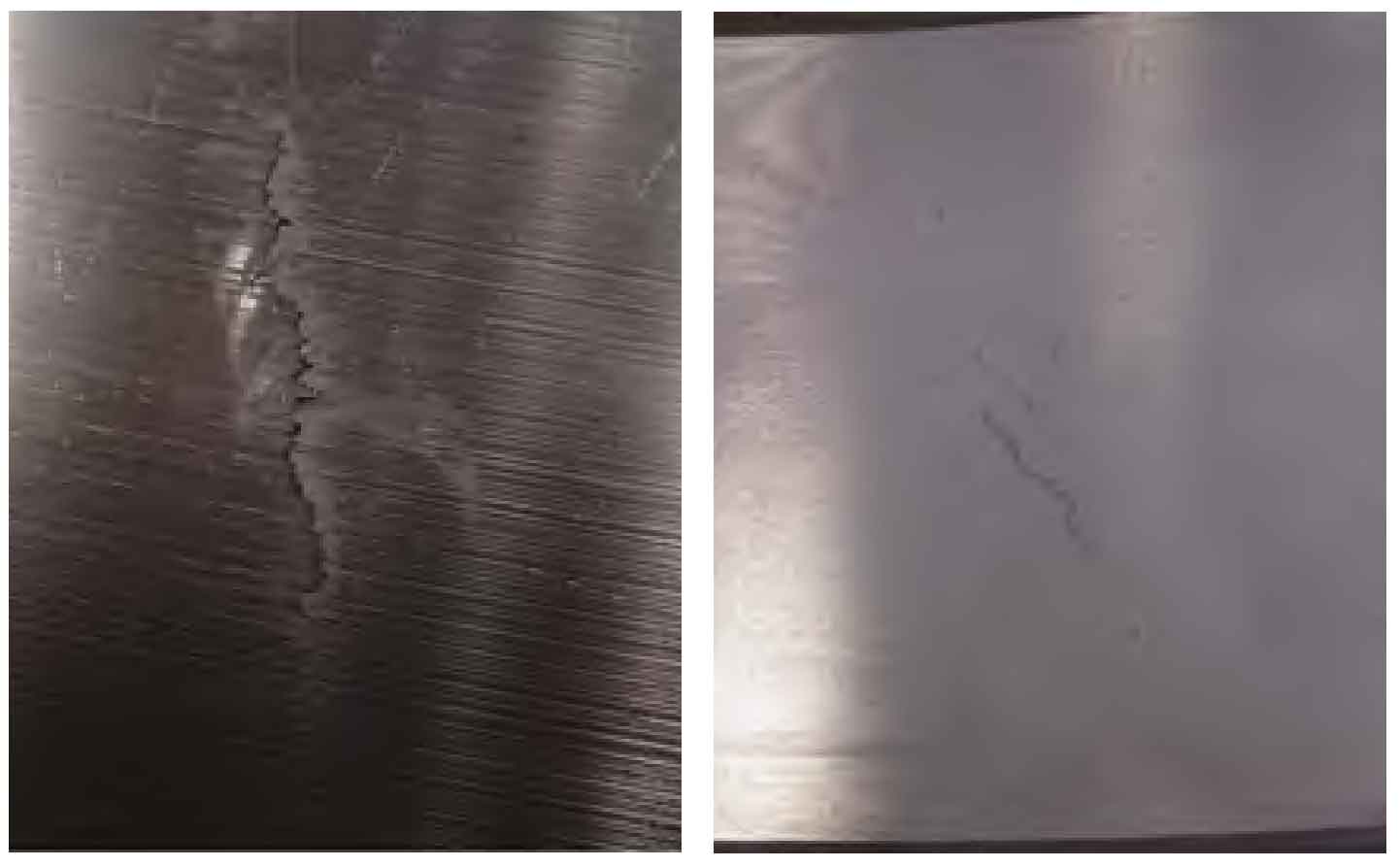
In the semi finishing stage after quenching and tempering, it was found that the nozzle end face had super detection casting defects. The macro morphology of the casting defects was surface cracks. In order to find out the causes, PT testing, on-site polishing and metallographic analysis were carried out on the casting defects, as shown in Figure 1.
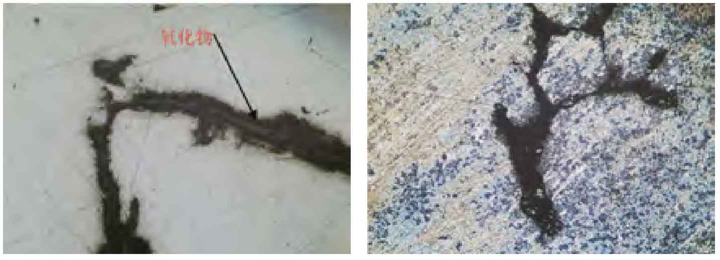
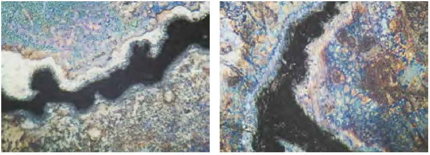
Grind and polish around the casting defects, and observe under the microscope that there are oxides in the cracks. As shown in Fig. 2 (a), the above oxides are produced under the later high-temperature oxidation. According to the production process of the supporting roller, it is indicated that the defect existed before the quenching and tempering treatment. In addition, it can be seen from Figure 2 (a) that the cracks are distributed along the semi reticulated or reticulated void morphology, which is a typical casting shrinkage porosity defect. Corrosion with 4% nitric acid alcohol can clearly observe the oxidation decarburization phenomenon of different degrees on both sides of the crack, as shown in Figure 2 (b). Therefore, it can be determined that the crack was a casting shrinkage porosity defect at the early stage, and the crack propagation connection was caused by thermal stress during the later quenching and tempering treatment.
The pouring system of the supporting roller is shown in Figure 3. In order to ensure the pouring process requirements of rapid and stable mold filling, the inner gate cuts upward along the bottom face of the outer rim. Through in-depth analysis based on the location of casting defects, it is found that the casting defects are located in the middle of the end face of the outer rim nozzle, distributed dispersedly, and coincide with the position of the inner gate of the supporting wheel. Therefore, it is judged that the occurrence of the above casting defects has a great relationship with the gating system.
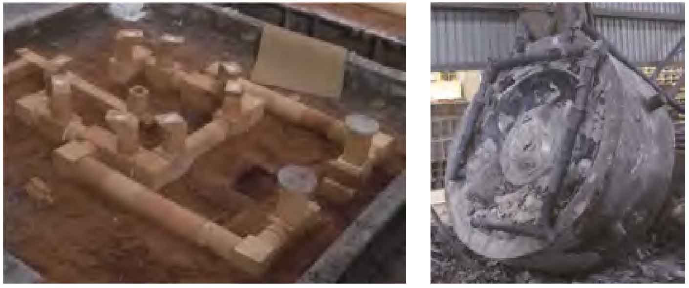
With the increase of casting idler size, its weight increases, and the amount of liquid steel required also increases significantly. However, the idler is poured in a single ladle, so the number of sprues during pouring remains the same, which is still 2. With the same pouring speed, the pouring time increases significantly, which leads to a significant increase in the amount of steel passing through the cross sprue and the inner sprue. Such as ϕ 2 The total weight of 200 mm supporting roller steel is about 35 t, about ϕ 1 1.8 times of 800 mm idler. As the superheated molten steel flows through the runner and ingate at the bottom for a long time during pouring, the superheat at this place increases sharply, forming a negative temperature gradient, thus increasing the risk of shrinkage casting defects at the corresponding ingate at the bottom. When the above shrinkage casting defects are serious, they can be found by nondestructive testing after rough machining, and when they are relatively minor, they will expand into cracks under the high stress state in the subsequent quenching and tempering process.
2. Countermeasures
According to the above analysis, the thermal impact of the bottom gating system on the supporting wheel body should be minimized.
On the one hand, the runner shall be placed in a rectangle to avoid placing along the circumference of the supporting roller and reduce the overlap between the runner and the supporting roller body. On the other hand, lengthening the length of the inner gate can increase a section of brick pipe, and increase the distance between the runner and the supporting wheel body.