
The Century Pavilion is one of the venues of the 10th China Flower Expo, with an overall appearance resembling a butterfly spreading its wings (Figure 1). The Century Pavilion has an east-west length of approximately 280m, a north-south length of approximately 115m, and a building height of approximately 15m.
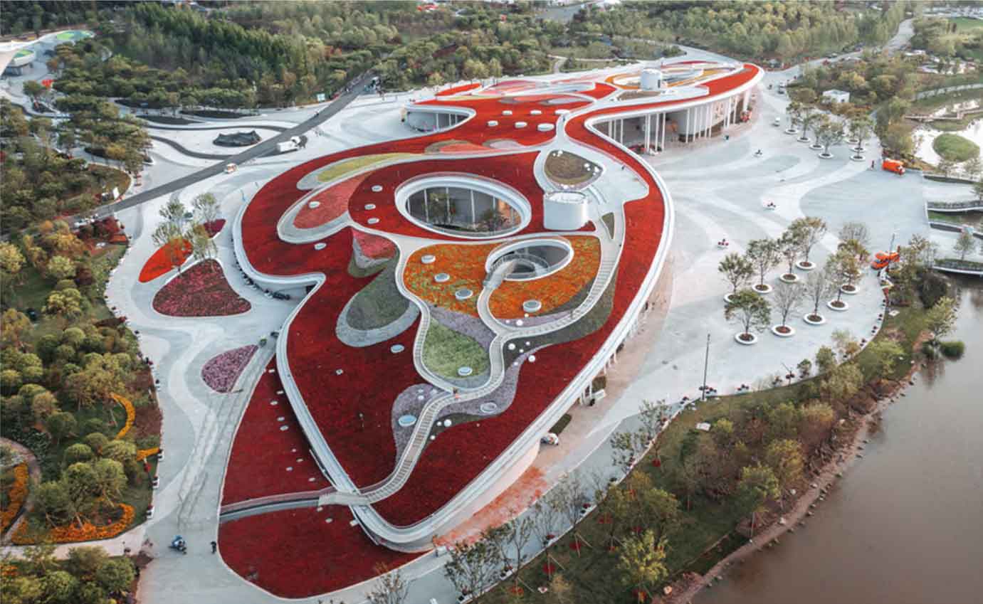
The roof is a free form curved prestressed concrete thin shell structure, supported by shear walls and slender sway columns. The typical thickness of the shell is 250mm.
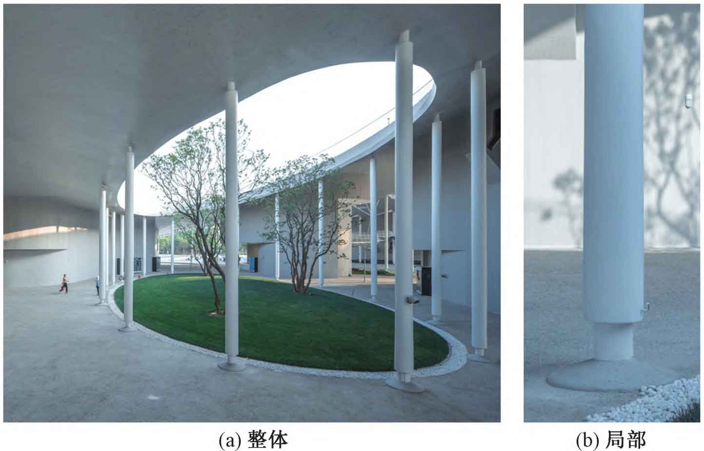
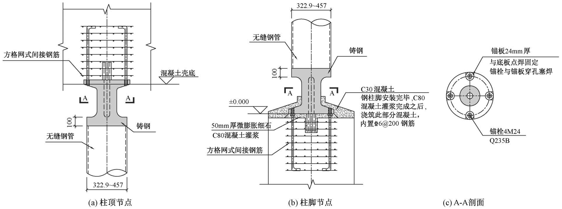
There are a total of 131 seamless steel pipe columns with 9 different cross-sections in the Century Museum (Figure 2), with a length of 6 1-13 6m, all steel pipes and grades are Q355B. To meet the architectural effect, the top and bottom sections of the steel pipe columns are partially retracted for later placement of lighting fixtures. To meet the needs of shape and load-bearing capacity, large-scale steel castings manufacturer design column foot nodes using integrated steel casting nodes, with steel grades of ZG340 ⁃ 550H. The detailed diagram of typical column base and column top nodes is shown in Figure 3.
For the design of steel column base nodes for large steel castings manufacturer (referred to as column base nodes in the following text due to the symmetry of column top and column base nodes), the design process and difficulties are first introduced. Then, the bearing capacity is verified using the universal finite element software ABAQUS, and the stress state of the column base is analyzed. Finally, the lateral stiffness of steel column models with different cross-sections, axial forces, and column heights is analyzed, Large scale steel castings manufacturer have proposed a simplified model of steel columns, providing a design basis for the connection form of steel columns in the overall model.
| Number | Seamless steel pipe diameter/mm | Seamless steel pipe wall thickness/mm | Seamless steel pipe length/mm | Steel casting length/mm | Neck outer diameter length/mm | Axial force/kN |
| ZJ2 | 355.6 | 16 | 10 000 | 525 | 180 | 2 500 |
| ZJ3 | 355.6 | 28 | 10 000 | 525 | 225 | 5 300 |
| ZJ6 | 457 | 30 | 13 000 | 525 | 225 | 6 000 |
Large scale steel castings manufacturer select three typical cross-sections based on the size of seamless steel pipes, and the cross-sectional parameters and axial forces are shown in Table 1. In the process of designing column bases, the following considerations are taken into account for the design of the neck section, top tray, and column base plate of large steel castings manufacturer.
1. Neck section
The outer diameter dimensions of the neck section are given according to the building requirements (Table 1). According to the “Technical Regulations for Steel Casting Structures” (JGJ/T395-2017) (referred to as the “Steel Casting Regulations”), the wall thickness of large steel castings designed by manufacturers should not exceed 150mm. Therefore, a cavity is set in the middle of the steel casting, and the neck section of large steel castings designed by manufacturers is circular (Figure 3 (c)). The wall thickness of the neck section is designed based on the axial force and bending moment it bears, as shown in equation , to ensure that its bearing capacity meets the requirements of the Steel Casting Code:
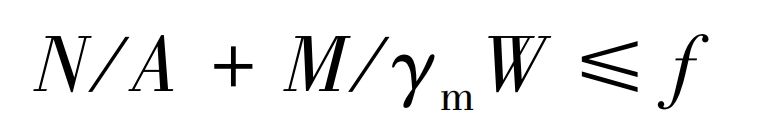
In the formula, N and M respectively represent the axial pressure and bending moment design values of the column base; A. W represents the cross-sectional area and cross-sectional modulus of the column base neck, respectively; γ M is the plastic development coefficient of the cross-section of a circular component; F is the design value for the tensile strength of large steel castings manufacturer.
Large scale steel castings manufacturer design steel castings with columns that have a large aspect ratio. The columns are designed as swinging columns, and the lateral bearing capacity is provided by shear walls. However, in practical construction, the column base cannot be fully hinged, and the column will share a certain bending moment. Therefore, if only the axial force acting on the swinging column is considered for section design, it will be unsafe. If the bending moment is determined based on the fixed connection of steel columns, the section bending capacity cannot meet the requirements of the Steel Casting Code under the outer diameter size required by the building. Therefore, in the preliminary design, the wall thickness of the neck section is temporarily calculated to have a stress ratio of less than 0 under axial force 6 OK, as shown in Table 2. Analyze the lateral stiffness of steel columns through finite element analysis, clarify the connection form of the column base, determine the bending moment acting on the column base, and verify the neck bearing capacity.
| Column base number | Neck cross-sectional outer diameter/mm | Neck section wall thickness/mm | N/Af | M fixed connection/ γ Wf | Total stress ratio |
| ZJ2 | 180 | 50 | 0.45 | 0.73 | 1.18 |
| ZJ3 | 225 | 80 | 0.54 | 0.48 | 1.02 |
| ZJ6 | 225 | 80 | 0.59 | 0.61 | 1.21 |
2. Top tray
The diameter of the top tray of large steel castings designed by manufacturers is the same as that of seamless steel pipes. The thickness t1 of the top tray is designed according to the cantilever plate, and the normal stress of the root section is verified σ、 Shear stress τ Whether the converted stress under the combined action of normal stress and shear stress meets the requirements of the Design Standard for Steel Structures (GB50017-2017) (referred to as the “Steel Standard”), the calculation formula is:
In the formula: D is the diameter of seamless steel pipe; Design the diameter of the cast steel neck for large steel castings manufacturer; Fv is a design value for the shear strength of large steel castings manufacturer.
| Column base number | Cantilever length/mm | Axial force/kN | Required thickness of top tray/mm | Edge thickness/mm | Chamfer radius/mm |
| ZJ2 | 88 | 2500 | 105.3 | 100 | 70 |
| ZJ3 | 65 | 5300 | 120.0 | 100 | 65 |
| ZJ6 | 116 | 6000 | 167.7 | 100 | 70 |
As shown in Table 3, according to the formula, the required thickness for the top tray of each steel casting is relatively large. Due to the increase in wall thickness, important indicators such as strength, elongation, and impact energy of large steel castings designed by manufacturers will decrease. Therefore, in the design, the tray thickness is taken as 100mm, and a chamfer is set between the tray and the neck (Figure 3) to meet the thickness requirements.
In addition, in the process of designing the top tray, two construction forms as shown in Figure 4 are considered, namely the cavity non penetrating form with better overall performance and the cavity penetrating form with relatively simple casting process designed by large steel castings manufacturer. Compare the stress performance of the two through subsequent finite element analysis.
3. Column base plate
The diameter D ′ of the column base plate designed by a large steel castings manufacturer is determined based on the local compressive bearing capacity of the concrete foundation. When checking the local compression of concrete, the area of local compression is usually used based on the area of the column foot bottom plate. For the column base in this project, due to the thicker neck wall thickness designed by the large steel castings manufacturer, the concrete compressive stress at the corresponding position is significantly higher than the surrounding area. If the local compressive area is still considered based on the area of the column base plate, it may overestimate the local compressive bearing capacity. Therefore, the following considerations were taken into consideration during the design:
1) Install grid type indirect steel bars, and control the ratio of column axial force to local compressive bearing capacity at 0 Below 6 (Table 4);
| Column base number | Uniformly distributed reaction force/MPa | Limit value of local compressive stress in concrete section/MPa | Axial force/kN | Local compressive bearing capacity/kN | Ratio |
| ZJ2 | 11.5 | 34.4 | 2500 | 8908 | 0.28 |
| ZJ3 | 24.5 | 49.1 | 5300 | 11036 | 0.48 |
| ZJ6 | 27.7 | 49.1 | 6000 | 11036 | 0.54 |
2) To avoid crushing the grouting material for the column base plate, the strength grade of the grouting material is increased to C80;
3) To avoid the thickness of the column base plate being too thin, the compressive stress on the concrete should be as uniform as possible.
The thickness of the column base plate designed by large steel castings manufacturer usually assumes a uniform distribution of stress at the bottom of the plate, and the maximum bending moment is determined based on the surrounding support conditions of each block. The required thickness t2 for the base plate of the column base in this project can be calculated according to the formula:
In the formula, D ‘represents the diameter of the column base plate, both of which are 525mm. For the column base ZJ6 with the highest axial force, according to the formula, the required thickness of the bottom plate of the column base reaches 129 7mm. Due to the uneven distribution of the reaction force on the base plate of the column, the closer the manufacturer of large steel castings designs the neck range of the steel castings, the greater the reaction force. Therefore, the traditional method of determining the thickness of the base plate of the column tends to be conservative. Meanwhile, due to the cross-sectional thickness effect of large steel castings designed by manufacturers, the strength decreases when the thickness exceeds 100mm. Considering the influence of concrete compression, the thickness of the base plate of the column base is temporarily designed as 100mm, and the bearing capacity of the column base plate is verified through finite element analysis.