
By analyzing the structure and technical requirements of the gearbox casting, a casting process plan was developed. Combined with Procast process simulation and the use of chill to improve the internal quality of the casting, the casting that meets the customer’s requirements was produced.
1. Introduction
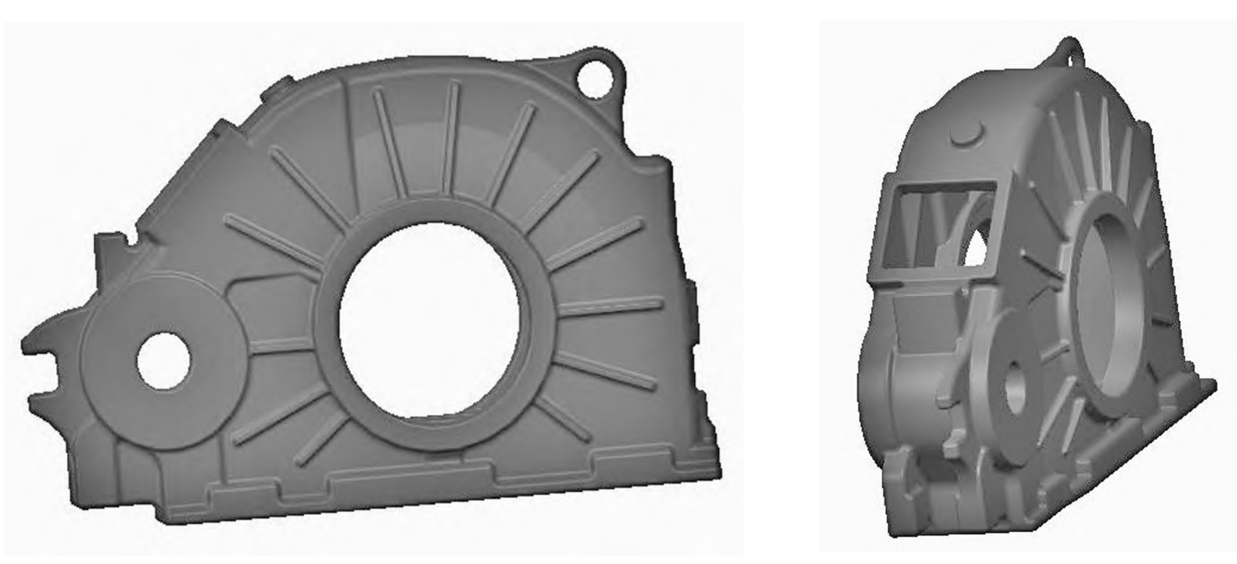
The gearbox casting is an important part of the transmission system, and its quality directly affects the performance and reliability of the equipment. The material of the gearbox casting is EN – GJS – 400 – 18 – LT (EN 1563), the weight of the part is 128.8 kg, and the weight of the casting is 162 kg. It is a box-like structure with an outline size of 961 mm × 596 mm × 252 mm.
2. Casting Process Plan and Procast Process Simulation
2.1 Casting Process Plan
According to the product structure and quality requirements, the middle parting of the gearbox casting was adopted in the process design. The 1140 mm × 1020 mm universal sand box was used for the sand box tooling. The inner cavity of the gearbox casting used a sand core structure, and the external lifting structure was designed with a sand core, with a total of 4 sand cores. The 1# and 2# sand cores in the inner cavity of the gearbox casting must first fall into the 3# sand core, and then fall into the lower mold together with the 3# sand core. The 4# sand core reserved a 20 mm sand filling area on the back and was pushed to the fixed position from the outside to the inside. The pouring system adopted a top-pouring closed pouring system. The choke section was on the inner gate. After the pouring started, the molten metal was easy to fill the pouring system, the slag-blocking ability was strong, the consumption of molten metal was less, and the cleaning was convenient. The inner gates were scattered on the flange surface for easy cleaning of the casting. According to the determination of the wall thickness and pouring time, the size of the pouring system was calculated by the choke section design method. The ratio of F_straight: F_transverse: F_inner was 2.04:1.64:1, the pouring temperature was 1350 °C to 1370 °C, and the pouring time was 25 s.
2.2 Procast Process Simulation
To verify the rationality of the casting process design of the gearbox casting, the process was simulated by Procast. The simulation results showed that there were shrinkage porosity defects. The shrinkage porosity positions were all at the structural hot spots, mainly because the wall thickness of the casting structure changed suddenly, and the isolated hot spots could not be fed. In order to prevent the occurrence of shrinkage porosity defects during the process test, chill was placed at the simulated defect positions for rapid cooling at the hot spots and insulation risers for liquid feeding.
- Process Test Verification and Results
3.1 First Test Verification
According to the process simulation results, chill and insulation risers were placed at the corresponding positions of the gearbox casting. The pouring temperature was 1370 °C, the pouring time was 23 s, the outer mold coating was alcohol-based coating flow coating, and the chill part was baked by a gas torch.
The results of the first test showed that: - The cleaned casting was in line with the designed three-dimensional shape after three-dimensional scanning (see the three-dimensional scanning comparison diagram in Figure 7).
- The X-ray flaw detection results showed that no defects were found at the positions with shrinkage porosity defects in the process simulation, but level 4 shrinkage porosity defects were found at the contact position between the hook and the gearbox casting(see the position of No. 29 piece in Figure 8), and level 3 shrinkage porosity was found at the connection between the external thick part and the gearbox casting (see the position of No. 13 piece in Figure 8).
- Surface porosity defects were found on the upper mold plane of the shot-blasted gearbox casting (see Figure 9), which affected the appearance quality of the casting.
- The low-temperature impact value of the attached casting sample was 8 J, 10 J, and 10 J, which did not meet EN 1563.
Analysis of the first test defects showed that:
- The defect positions of No. 13 and No. 29 pieces in the ray flaw detection were at the connection position with the box, which belonged to an independent hot spot. It was analyzed that the wall thickness at this connection part was thicker than that at other parts without connection, and chill needed to be added to speed up the cooling speed at these two places to reduce or eliminate the shrinkage porosity defects at these two places.
- The position of the surface porosity defect after shot blasting was on the opposite side of the pouring system and far away from the pouring system. It was analyzed that when the molten iron flowed to this place, the temperature decreased, resulting in the gas generated by the sand core could not be discharged in time, resulting in the surface porosity. The pouring temperature should be increased or the flow of molten iron to this place should be accelerated. The process measure was to increase the pouring temperature and raise the side of the pouring system to accelerate the flow of molten iron to the opposite side of the pouring system.
- For the problem of unqualified low-temperature impact of the attached casting sample, it was analyzed that the current mass fraction of Si was 2.2% – 2.5%. A certain amount of Si could promote graphite and prevent the generation of cementite, but Si would increase the brittle transition temperature of the material and reduce the toughness. The measure was to reduce the mass fraction of Si to 2.0% – 2.2%.
3.2 Second Test Verification
3.2.1 Process Improvement in the Second Test
Based on the analysis results of the first test, the following measures were taken: 1) Add rivets and round steel as chill at the positions of No. 13 and No. 29 pieces to reduce the shrinkage porosity defects at these two places (see Figure 10); 2) Increase the pouring temperature to 1400 °C, and raise the side of the pouring system by 60 mm to reduce the surface porosity defects; 3) Reduce the mass fraction of Si to 2.0% – 2.2% during melting to improve the low-temperature toughness of the attached casting sample.
3.2.2 Results of the Second Test
- The X-ray flaw detection results showed that the positions of No. 29 and No. 13 pieces were at level 1, which met the requirements of the drawing (see Table 1).
- After shot blasting, there were no surface porosity defects on the casting surface, and the casting surface quality was good.
- The low-temperature impact value of the attached casting sample was 12 J, 14 J, and 10 J, which met EN 1563.
- Conclusions
- The use of reasonable chill and riser structures can ensure the internal quality of important parts of the casting.
- Increasing the pouring temperature and raising one side of the pouring system can increase the flow speed of the molten iron and reduce the surface porosity defects on the side far away from the pouring system.
- A reasonable Si content can improve the low-temperature toughness of the attached casting sample.
Table 1: Flaw Detection Results of the Gearbox Casting
| Piece Number | Defect Analysis | Level | Piece Number | Defect Analysis | Level |
|---|---|---|---|---|---|
| 1 | A | 1 | 19 | A | 1 |
| 2 | A | 1 | 20 | A | 1 |
| 3 | Ce | 1 | 21 | 1 | 1 |
| 4 | Cb | 1 | 22 | 1 | 1 |
| 5 | 1 | 1 | 23 | A | 1 |
| 6 | Cb | 1 | 24 | 1 | 1 |
| 7 | 1 | 1 | 25 | 1 | 1 |
| 8 | 1 | 1 | 26 | Ce | 2 |
| 9 – 1 | 1 | 1 | 27 | 1 | 1 |
| 9 – 2 | 1 | 1 | 28 | A | 1 |
| 9 – 3 | 1 | 1 | 29 | Ce | 1 |
| 9 – 4 | 1 | 1 | 30 | 1 | 1 |
| 9 – 5 | 1 | 1 | 31 | Ce | 1 |
| 10 | 1 | 1 | 32 | Ce | 1 |
| 11 | 1 | 1 | 33 | 1 | 1 |
| 12 | 1 | 1 | 34 | 1 | 1 |
| 13 | Ce | 1 | 35 | 1 | 1 |
| 14 | 1 | 1 | 36 | 1 | 1 |
| 15 | 1 | 1 | 37 | Ce | 1 |
| 16 | 1 | 1 | 38 | 1 | 1 |
| 17 | A | 1 | —- | —- | —- |
| 18 | A | 1 | —- | —- | —- |
This paper only provides a brief overview of the research on the casting technology of the gearbox casting. In actual production, more detailed process parameters and quality control measures need to be determined based on specific conditions to ensure the quality and performance of the casting. Further research and optimization can also be carried out to improve the casting process and product quality.