This article focuses on the casting process of the L21 front-end case. It analyzes the porosity problems encountered in production and formulates improvement measures. By strengthening the gas exhaust, gas introduction, and gas storage of the mud core, optimizing the pouring system, and adopting the bottom-pouring filter piece pouring process, the aims of reducing the molten iron turbulence and gas entrapment during the pouring process are achieved, the porosity defects of the casting are reduced, and the surface quality of the casting is improved.
1. Introduction
The casting production of the front-end case is challenging due to its complex structure and numerous internal cavities. The main problems in the casting of the front-end case are porosity and shrinkage-like defects, which affect the casting quality. The concession rate and scrap rate of the casting account for a large proportion, and the complete qualification rate is relatively low. Through process improvement, mainly optimizing the mud core gas exhaust and the pouring system, the previous porosity problems have been controlled, and the casting quality has basically stabilized, meeting the requirements of mass production.
2. Casting Structure Characteristics and Technical Requirements
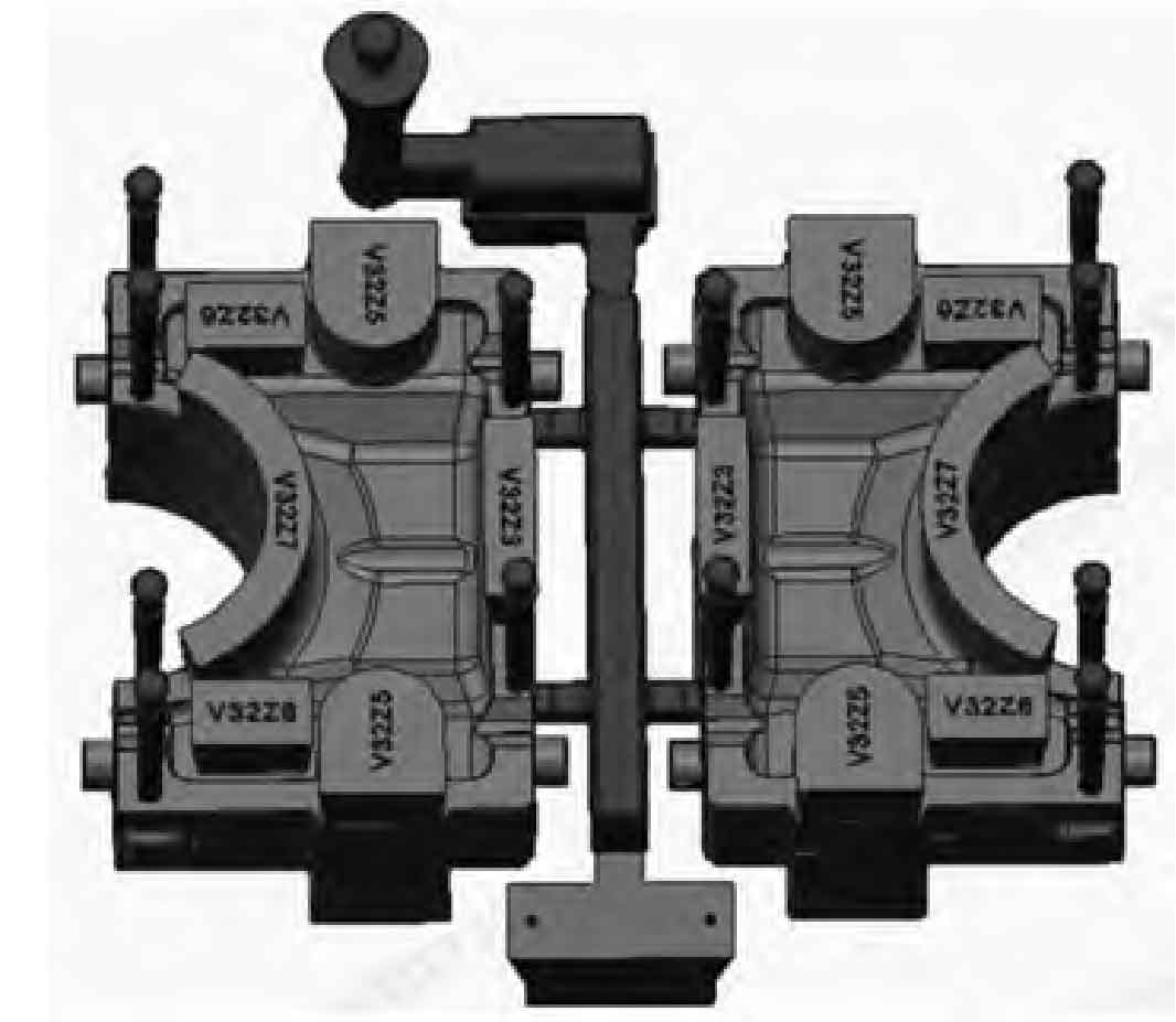
The L21/31 front-end case casting has a rough weight of 2,180 kg and an outline dimension of 1800 mm × 1100 mm × 950 mm. Its internal structure is extremely complex, with a total of 27 sand cores in the upper, middle, and lower layers forming multiple interconnected internal cavity structures. The distribution of the cavity mud core is shown in Figure 1. The main wall thickness of the L21/31 front-end cavity casting is 12 mm, and the maximum wall thickness is 125 mm. The large difference in wall thickness is prone to casting defects such as porosity and shrinkage porosity, which ultimately lead to leakage and scrapping of the casting during the hydraulic pressure test and air pressure test. The casting material is HT300, and the mechanical performance requirements are that the tensile strength σb ≥ 300 N/mm² and the HB hardness is 185 – 278.
3. Existing Problems and Causes
3.1 Porosity Defects
Since the trial production of the L21/31 front-end case started in 2013, there has been a “stagnant gas” phenomenon on the upper surfaces of the upper, middle, and lower layers. The porosity defects caused by the “stagnant gas” of the casting are shown in Figure 2. The number is not large, but the volume is relatively large, the hole wall is smooth, and it appears on the surface layer of the casting. The shapes are mostly close to pear-shaped, oval, or circular.
3.2 Causes of Porosity Defects
3.2.1 Invasive Porosity Mechanism
From the analysis of the mechanism of invasive porosity, when the liquid metal enters the sand mold, the sand mold or sand core will generate a large amount of gas under the high temperature action of the molten metal. As the temperature rises and the amount of gas increases, the pressure of the gas at the metal-mold interface continuously increases. When the pressure of the local gas on the interface is higher than the external resistance, the gas will invade the liquid metal and form bubbles on the mold wall. After the bubbles are formed, they will detach from the mold wall and float into the liquid metal in the cavity. When the bubbles are not in time to float and escape, invasive porosity will be formed in the metal.
3.2.2 Pouring System Problem
The previous pouring system has always arranged the runner on the upper box, and the inner gate directly introduces into the bottom of the casting with a ceramic tube. Since the height difference of the inner gate is close to 1000 mm, the molten iron obtains a relatively high flow velocity in the vertical inner gate before rushing into the cavity. When rushing into the cavity, the high-speed flowing molten iron is extremely prone to backflow. The complex cavity structure is not conducive to the gas floating upwards. If the gas wrapped in the molten iron is not in time to float and discharge, most of them will finally stop moving on the surface or the surface layer, eventually forming porosity defects. Using software to simulate the molten iron filling process and track the particle motion state as shown in Figure 3, there are obvious phenomena such as turbulence and gas entrapment.
3.2.3 Mud Core Gas Exhaust Problem
Due to the complex structure of the L21 front-end case, the number of mud cores in the cavity is large, and the layout method is mainly vertical, horizontal, and laminated distribution, which is not conducive to the gas exhaust of the mud core. In addition, the size of the 24# mud core in the upper part of the cavity (see Figure 1) is large (the horizontal cross-sectional dimension is approximately 1300 mm × 850 mm). Besides its large gas generation amount of the mud core itself, it also hinders the smooth gas exhaust of the lower mud core and the rapid discharge of the cavity gas to a certain extent.
4. Process Improvement Directions and Processes
4.1 Core Gas Exhaust
4.1.1 Increasing the Gas Exhaust Area of the 24# Mud Core
The gas generation amount of this mud core is large. To ensure that the gas in the mud core is discharged as soon as possible during the heating process and minimize the gas migrated from the bottom and around the mud core from invading the molten iron and being unable to float and discharge in time, through experimentation and discussion design, the center position of the top of the mud core is hollowed out (ensuring that the sand eating amount around the mud core is not less than 200 mm), and the recycled coke is pre-buried. The advantages of doing this for the mud core gas exhaust are reducing the gas generation amount of the mud core itself, leaving a gas exhaust channel for the gas discharge in the mud core, and also increasing a certain storage space for the gas migrated from the mud core, improving the tendency of the gas in the mud core to be discharged into the cavity, as shown in Figure 4.
4.1.2 Gas Exhaust of Other Mud Cores
After experimentation, the method of “rope extraction + pre-buried ventilation rope” is adopted, as shown in Figure 5. When the mud core is molded, a ventilation rope is placed along the core skeleton (select a ventilation rope with a diameter of φ6 mm – φ8 mm according to the size of the mud core). After the box is assembled and the core is placed, the gas exhaust channel of the mud core is led out from the core head to the outside of the sand box with a rope. After the sand is filled, the rope is pulled out. The benefits of doing this are that the ventilation rope is made of nylon material weaving and has certain toughness and strength. After the rope is pulled out, a stable gas exhaust channel can be formed between the mud core and the outside. In addition, this method also reduces the safety risk in the operation process and has a certain effect on preventing the porosity quality defects of the casting.
4.1.3 Setting of Gas Outlet Risers
The 24# mud core is basically covered on the upper part of the cavity, which is not conducive to the discharge of the cavity gas, and the location where the porosity defects often occur is mostly located at the lower part of this mud core. In order to enable the gas at the bottom of the mud core to be discharged smoothly from the inside of the cavity, at the location where the porosity defects often occur (the part where the gas is easily accumulated in the cavity), a gas outlet riser is added. As shown in Figure 6, the riser passes through the 24# mud core, allowing the gas to be directly removed from the gas outlet riser on the upper box.
4.2 Pouring System Improvement
4.2.1 First Pouring System Improvement
The improvement of the pouring system is mainly to reduce the turbulence phenomenon during the molten iron filling. After technical exchanges with the user, the runner is placed at the bottom of the casting. Through the slow-flow effect of the bottom horizontal runner, the filling speed of the molten iron at the inner gate is reduced.
A completely bottom-pouring pouring system scheme is designed in combination with the actual situation. As shown in Figure 7, the runner is located at the bottom of the casting to buffer the molten iron in the sprue and reduce the filling speed. During the trial production period, based on the verification results, it has been improved several times on a small scale on this basic process. After the trial production, placing the runner at the bottom, the number of porosity defects in the casting has been significantly reduced, but not completely eliminated.
4.2.2 Second Pouring System Improvement
According to the analysis of the first test results, it is considered that the improved mud core gas exhaust method is relatively reasonable, and the molten iron filling speed has slowed down. However, in terms of the quality results of the produced castings, the porosity defects have not been eliminated, so there is still room for process improvement. After communicating with the FOSECO engineer, it is believed that the completely bottom-pouring pouring design is helpful for the project improvement goal. In order to further reduce the molten iron turbulence and backflow phenomenon and keep the cavity liquid level rising steadily as much as possible, it is decided to apply the filtration technology to add a filter piece at the inner gate. This can not only improve the filling speed but also play a role in slag retention. Figure 8 shows the schematic diagram of the filter piece pouring system scheme.
5. Production Verification
According to the improved and optimized core gas exhaust and bottom-pouring filter piece pouring process scheme for molding, box assembly, and pouring, after cleaning, the frequently-occurring defect locations in the previous period are inspected and confirmed, and the casting surface quality is good. After continuous production of 5 pieces, it is found that the surface quality of the roughcast has been greatly improved, the inner cavity wall is smooth and without defects, and no porosity is found. The casting surface quality status is shown in Figure 9, indicating that good improvement effects have been achieved.
6. Conclusions
6.1 Effect of Core Gas Exhaust Optimization
By strengthening the gas exhaust, gas introduction, and gas storage of the casting mold and mud core, and orderly transferring the gas generated in the casting cavity and mud core during the pouring process, the porosity defects of the casting can be effectively improved, and the appearance quality of the casting can be enhanced.
6.2 Advantage of Bottom-Pouring Filter Piece Pouring Process
The front-end case adopts the bottom-pouring open filter piece pouring process, which can reduce the turbulence during the pouring process, make the filling process stable, and simultaneously reduce the gas entrapment in the molten metal during the pouring process, reducing the occurrence of porosity problems.
7. Future Research Directions and Suggestions
7.1 Further Optimization of Mud Core Gas Exhaust
Although measures have been taken to improve the gas exhaust of the mud core, further research can be conducted to explore more efficient gas exhaust methods. For example, studying the application of new materials or structures for the mud core to enhance its gas permeability and reduce gas accumulation. Additionally, optimizing the layout and size of the gas exhaust channels to ensure smoother gas discharge.
7.2 Continuous Improvement of Pouring System
The current pouring system improvements have achieved certain results, but there is still room for optimization. Future research could focus on further reducing the turbulence and backflow of molten iron. This may involve exploring more advanced pouring system designs or using new technological means to control the flow of molten iron more precisely. For instance, investigating the use of intelligent control systems to adjust the pouring parameters in real time according to the actual situation during the pouring process.
7.3 Quality Monitoring and Control
Strengthening the quality monitoring and control of the casting process is crucial. Developing more accurate and efficient detection methods for porosity and other defects to ensure timely discovery and treatment of problems. At the same time, establishing a comprehensive quality management system to track and analyze the quality data of each production batch, so as to continuously improve the process and product quality.
7.4 Material and Process Integration Research
Considering the interaction between the casting material and the process, further research can be carried out on the compatibility of the material and the optimized casting process. For example, studying how the characteristics of the HT300 material affect the formation of porosity and how to adjust the process parameters accordingly to achieve better casting quality. This requires in-depth cooperation between material science and casting technology to promote the overall improvement of casting technology.
In conclusion, the optimization and improvement of the casting process for the L21 front-end case have achieved certain results, but there are still many aspects that need to be continuously explored and improved to further enhance the casting quality and production efficiency, and meet the higher requirements of the industry.
[Here you can add some relevant pictures such as the actual casting, the layout of the mud core, the improved gas exhaust structure, the pouring system, etc. to make the article more vivid and intuitive. Since I can’t directly generate pictures, you can replace this part with actual pictures when using it.]
This article provides a comprehensive analysis and improvement measures for the casting process of the L21 front-end case, aiming to solve the porosity problems and improve the casting quality. Through the optimization of the mud core gas exhaust and the pouring system, certain achievements have been made, but there is still a need for continuous research and improvement in the future to better meet the production needs.
8. Comparison with Similar Casting Processes
In the field of casting, there are many similar complex casting processes. For example, the casting of engine blocks also has challenges such as complex internal structures and the need to control porosity defects. By comparing with the casting process of engine blocks, we can find some common points and differences.
Similarities:
- Both require careful design of the core structure to form the internal cavities. In the case of the L21 front-end case and engine blocks, the arrangement and gas exhaust of the cores are crucial to ensure the quality of the castings.
- The optimization of the pouring system is essential. Just as in the L21 front-end case, reducing turbulence and ensuring a stable filling process is also a key consideration in engine block casting to prevent defects such as porosity and inclusions.
Differences:
- The specific shape and size of the castings are different, which leads to different requirements for the design of the core and the pouring system. For example, the engine block may have more complex cooling channels and oil passages, requiring more precise core design and pouring control.
- The materials used may vary. While the L21 front-end case uses HT300, engine blocks may use different alloy materials with specific mechanical properties and casting characteristics, which affect the process parameters and heat treatment methods.
9. Economic Impact of Process Improvement
The process improvement of the L21 front-end case has significant economic implications.
Reduction in Scrap Rate: By reducing the porosity defects and improving the quality of castings, the scrap rate has decreased. This directly saves the cost of raw materials and production. Fewer defective castings mean less waste of the expensive HT300 material and the labor and energy invested in the production process.
Increased Production Efficiency: The optimized casting process, such as the improved pouring system and core gas exhaust, has led to a more stable production process. This reduces the time required for troubleshooting and rework, thereby increasing the production output per unit time. With higher production efficiency, the overall production cost per casting is reduced, making the product more competitive in the market.
Cost of Process Improvement: Although there are initial costs associated with implementing the process improvements, such as the cost of redesigning the core structure, adding gas outlet risers, and adopting new pouring system technologies (like using filter pieces), the long-term economic benefits outweigh these initial investments. The reduced scrap rate and increased production efficiency quickly offset the cost of improvement, resulting in overall cost savings and improved profitability for the manufacturing enterprise.
10. Environmental Considerations
In the context of modern manufacturing, environmental considerations are becoming increasingly important. The casting process improvement of the L21 front-end case also has some impacts on the environment.
Reduction in Waste Generation: The decrease in scrap castings means less solid waste that needs to be disposed of. This reduces the burden on the environment and saves landfill space. Additionally, the optimized process may also reduce the consumption of some auxiliary materials, such as the amount of sand used in the molding process, further reducing the environmental impact associated with material extraction and disposal.
Energy Conservation: A more stable and efficient casting process may lead to energy savings. For example, if the improved pouring system reduces the need for excessive reheating or correction of defective castings, it can reduce the overall energy consumption in the production process. This is not only beneficial for cost reduction but also aligns with the goal of reducing carbon emissions and environmental protection.
Emission Reduction: The reduction in defects and the optimization of the process can also lead to a decrease in the emission of pollutants during the casting process. Fewer defective castings mean less need for secondary processing, which may reduce the emission of harmful gases and particulate matter. Additionally, the improved core gas exhaust system can better control the release of volatile organic compounds and other pollutants generated during the heating and curing of the core, further improving the environmental performance of the casting process.
11. Case Studies of Successful Applications
To further illustrate the effectiveness of the process improvement measures, here are some case studies of successful applications of the optimized L21 front-end case casting process.
Case Study 1: Company A
Company A implemented the improved casting process, including the enhanced core gas exhaust and the bottom-pouring filter piece pouring system. Before the improvement, their casting rejection rate due to porosity defects was around 20%. After the implementation, the rejection rate decreased to less than 5%. This not only improved the quality of their products but also significantly reduced the production cost due to fewer rework and scrap. The surface quality of the castings was also greatly enhanced, meeting the higher requirements of their customers. As a result, Company A was able to increase its market share and improve its competitiveness in the industry.
Case Study 2: Company B
Company B focused on optimizing the 24# mud core gas exhaust as per the proposed measures. They hollowed out the top center of the mud core and added a gas storage space with pre-buried recycled coke. By doing so, they effectively reduced the gas pressure inside the core during the casting process. The number of porosity defects in the castings produced by Company B was reduced by over 70%, and the overall mechanical properties of the castings were also improved. This enabled them to successfully complete a large order for high-quality L21 front-end cases, enhancing their reputation and profitability.
12. Challenges and Solutions in the Implementation Process
During the implementation of the process improvement measures, several challenges were encountered, and the corresponding solutions were found.
Challenge 1: Technological Adaptation
The new core gas exhaust and pouring system technologies required some adjustments and training for the production workers. Some workers were initially unfamiliar with the operation of the new process, which affected the production efficiency and quality.
Solution: The company provided comprehensive training programs for the workers, including theoretical knowledge and practical operation training. They also established a technical support team to provide on-site guidance and troubleshooting during the initial implementation stage. This helped the workers quickly master the new technologies and ensure the smooth progress of the production process.
Challenge 2: Equipment Modification
To implement the bottom-pouring filter piece pouring system, some modifications to the existing casting equipment were necessary. This required additional investment and time for equipment installation and 调试.
Solution: The company carefully planned the equipment modification project, collaborating with equipment suppliers to ensure the compatibility and effectiveness of the new system. They also scheduled the equipment modification during a planned production downtime to minimize the impact on production. By doing so, they successfully implemented the new pouring system without significant disruption to the production schedule.
Challenge 3: Cost Control
The initial cost of implementing the process improvements, including the cost of new materials (such as filter pieces) and equipment modification, was relatively high. There was a need to ensure that the long-term economic benefits could justify the initial investment.
Solution: The company conducted a detailed cost-benefit analysis before implementing the improvements. They estimated the potential savings in terms of reduced scrap rate, increased production efficiency, and improved product quality. Based on this analysis, they 制定了 a phased implementation plan to gradually introduce the improvements. This allowed them to monitor the actual economic benefits during the implementation process and make adjustments if necessary. Additionally, they actively explored ways to reduce the cost of materials and equipment, such as negotiating better prices with suppliers and optimizing the equipment configuration.
13. Future Trends in Casting Process Technology
Looking ahead, there are several trends that are likely to impact the casting process technology for the L21 front-end case and similar castings.
Digitalization and Simulation: The use of digital technologies and simulation software will continue to grow. Manufacturers will increasingly rely on advanced simulation tools to optimize the casting process before actual production. This can help predict and prevent defects, such as porosity, and improve the overall quality and efficiency of the casting process. For example, virtual reality and augmented reality technologies may be used for training and process visualization, enabling workers to better understand and operate the complex casting process.
Automation and Intelligent Manufacturing: Automation will play a more important role in casting production. Robots and automated systems can be used for tasks such as mold making, core assembly, and pouring, reducing human error and improving production consistency. Intelligent manufacturing systems can also monitor and adjust the process parameters in real time based on sensor data, ensuring a more stable and optimized casting process.
Sustainable and Green Casting: With increasing environmental concerns, the casting industry will focus more on sustainable and green manufacturing. This includes the development and application of new materials and processes that reduce waste, energy consumption, and emissions. For instance, the use of renewable materials in mold making and the exploration of more energy-efficient casting methods will be important research directions.
Additive Manufacturing in Casting: Additive manufacturing technologies, such as 3D printing, are starting to have an impact on the casting industry. They can be used to produce complex molds and cores with high precision, reducing the need for traditional machining and assembly processes. This can lead to shorter production cycles and lower costs, as well as improved design flexibility for castings.
14. Conclusion
The optimization and improvement of the casting process for the L21 front-end case have been a comprehensive and successful effort. By addressing the issues of porosity defects through measures such as enhancing core gas exhaust and improving the pouring system, significant improvements have been achieved in terms of casting quality, surface finish, and production efficiency. The economic benefits, including reduced scrap rate and increased productivity, have made the process improvement a valuable investment for manufacturing enterprises. Additionally, the environmental considerations have also been taken into account, with the improved process leading to reduced waste generation and lower emissions.
Looking forward, the casting process technology will continue to evolve, and the trends towards digitalization, automation, sustainability, and additive manufacturing will offer new opportunities and challenges. Manufacturers need to stay updated with the latest technologies and trends to further improve the casting process and meet the ever-increasing demands of the market. By continuously learning and innovating, the casting industry can produce higher quality castings with better performance and lower costs, while also fulfilling its environmental responsibilities.