
Abstract
This article focuses on the cylinder body casting of an 11-liter 6-cylinder engine of a commercial vehicle. By systematically analyzing the flow and temperature fields of the original pouring system’s molten iron filling process, a new type of pouring system was designed. Through batch production verification, the local porosity defect of the casting was effectively solved. At the same time, the gate position was improved to avoid heat buildup in the tile seat area, and the material performance of the casting tile seat area was improved.
1. Introduction
The engine cylinder body is a critical component in the automotive industry, responsible for housing the pistons and connecting rods. Its quality directly affects the performance and reliability of the engine. However, during the casting process of the cylinder body, various defects may occur, such as porosity, shrinkage, and hot spots, which can significantly impair the mechanical properties and service life of the casting. Among these defects, porosity is one of the most common and detrimental issues.
In this study, we address the porosity issue in the casting of an 11-liter 6-cylinder engine cylinder body produced by our company. By analyzing the flow and temperature fields of the original pouring system using computational fluid dynamics (CFD) simulations, we identified the root causes of the porosity defects. Based on these findings, we designed a new pouring system to optimize the iron filling process and eliminate the porosity defects. Additionally, we modified the gate positions to avoid heat buildup in the tile seat area, thereby improving the material properties of this critical region.
The remainder of this article is structured as follows: Section 2 provides an overview of the casting process and the original pouring system. Section 3 presents the defect analysis, including the location, morphology, and causes of the porosity defects. Section 4 describes the design of the new pouring system and the improvements made to the gate positions. Section 5 presents the results of batch production verification and discusses the effectiveness of the new pouring system. Finally, Section 6 concludes the study and summarizes the key findings.
2. Overview of the Casting Process and Original Pouring System
2.1 Casting Process Description
The cylinder body casting under study is produced using the following process:
- Material: HT250 gray cast iron
- Casting Weight: Approximately 240 kg
- Main Wall Thickness: 5 mm
- Molding Material: Clay wet sand
- Molding Method: HWS hydrostatic molding
- Pouring Position: Horizontal pouring, one casting per mold
- Melting Equipment: Medium frequency induction furnace
- Pouring Machine: KW pouring machine
- Pouring Temperature: 1440 °C ± 10 °C
- Pouring Speed: Approximately 14–17 kg/s
2.2 Original Pouring System Design
The original pouring system for the cylinder body casting. It consists of a runner, seven branch gates, and three layers of ingates. The ingates are located on the two crankshaft bearing caps of the cylinder block and the oil pan flange of the lower case. This design aims to achieve a relatively smooth filling process with even iron flow through each gate.
However, during actual production, two major issues were encountered:
- Porosity Defects: Hole-like defects frequently occur near the crankcase area of the upper case, primarily in the thin-walled sections at the highest point.
- Low Mechanical Properties of Bearing Cap Area: The mechanical properties of the crankshaft bearing cap area are on the lower limit.
3. Defect Analysis
3.1 Location and Morphology of Defects
3.1.1 Location of Defects
The porosity defects in the 11-liter cylinder body casting primarily occur near the crankcase area of the upper case, specifically in the thin-walled sections at the highest point .
3.1.2 Morphology of Defects
The defects appear as spherical holes with smooth walls . In severe cases, the walls may be penetrated, rendering the casting scrap.
3.2 Microscopic Analysis of Defects
3.2.1 Metallographic Analysis
Metallographic examination of the defect area reveals a combination of flake graphite and fine punctate graphite .
3.2.2 Scanning Electron Microscopy (SEM) and Energy Dispersive Spectroscopy (EDS) Analysis
SEM analysis of the defect area at magnifications of 45× and 90× shows a smooth internal surface with a waist-circular cross-section and obvious holes . EDS analysis detects high oxygen content (30.48% by weight), indicating that the defects are porosity (Table 1).
Table 1: EDS Analysis Results of Defect Area
| Element | Concentration | Intensity Correction | Weight Percentage | Atomic Percentage |
|---|---|---|---|---|
| C K | 12.56 | 3.7006 | 3.93 | 9.18 |
| O K | 30.48 | 1.2316 | 28.63 | 50.19 |
| Na K | 0.65 | 0.7010 | 1.07 | 1.31 |
| Mg K | 0.21 | 0.6640 | 0.37 | 0.43 |
| Al K | 3.05 | 0.7758 | 4.55 | 4.73 |
| Si K | 3.43 | 0.8476 | 4.69 | 4.68 |
| P K | 0.48 | 1.2390 | 0.45 | 0.41 |
| S K | 1.05 | 0.9774 | 1.24 | 1.09 |
| K K | 1.21 | 1.1357 | 1.23 | 0.88 |
| Ca K | 1.23 | 1.0868 | 1.31 | 0.92 |
| Ti K | 4.20 | 0.9255 | 5.25 | 3.07 |
| Cr K | 1.13 | 0.9557 | 1.36 | 0.74 |
| Mn K | 3.54 | 0.8756 | 4.68 | 2.39 |
| Fe K | 30.75 | 0.9984 | 35.63 | 17.90 |
| Ni K | 2.65 | 0.8695 | 3.53 | 1.68 |
| Ce L | 1.54 | 0.8544 | 2.09 | 0.42 |
| Total | 100.00 |
3.3 Causes of Porosity Defects
Porosity typically occurs in the upper surface thin-walled sections and highest points of castings. In this case, the porosity defects are located at the highest point of the upper case. The possible causes of porosity defects include:
- Low Pouring Temperature: The actual pouring temperature was 1440 °C, with a temperature drop of approximately 3.3 °C per minute during pouring. The pouring temperature was deemed reasonable, and temperature drop had minimal impact on porosity.
- Inadequate Ventilation: Ventilation was confirmed to be smooth during pouring, ruling out inadequate ventilation as a cause.
- Iron Runout: No iron runout was observed during pouring, ruling out this as a cause.
- Unreasonable Pouring System Design: CAE filling simulation analysis revealed that the first flow of cold iron water collected in the crankcase area, leading to porosity.
3.4 Analysis of Low Mechanical Properties in Bearing Cap Area
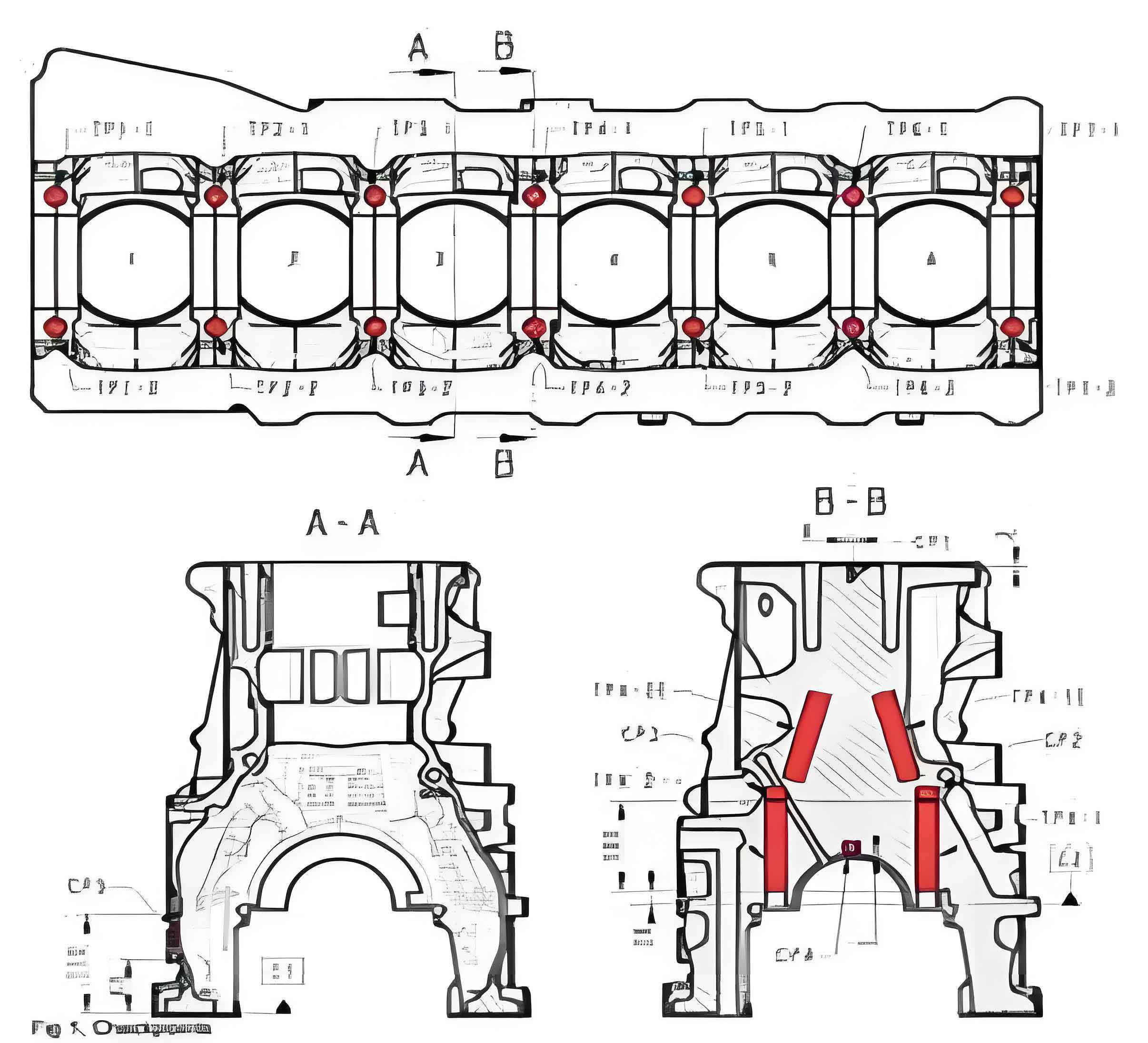
3.4.1 Mechanical Property Requirements and Sampling Locations
The mechanical property requirements for the bearing cap area are shown in Table 2, with sampling locations indicated.
Table 2: Mechanical Property Requirements for Bearing Cap Area
| Test Position | Minimum Tensile Strength / MPa | Minimum Hardness (HBW, 5/750) | Maximum Hardness (HBW, 5/750) |
|---|---|---|---|
| TPX-1 (4th Bearing Cap Partition Wall) | 195 | 170 | 230 |
| TPX-2 (4th Bearing Cap Partition Wall) | 195 | 170 | 230 |
3.4.2 Material Analysis of Bearing Cap Area
3.4.2.1 Metallographic Analysis
The graphite in the bearing cap area is primarily A95+B type, with most graphite lengths at grades 3–4 and a few at grade 5 .
3.4.2.2 Mechanical Property Analysis
The mechanical properties of 15 batches of samples from the 4th bearing cap partition wall are shown in Table 3. The tensile strength and hardness are close to the lower limit of the technical requirements, with large variations. The continuous inflow of iron water at high temperatures leads to slow cooling and the formation of coarse flake graphite, which affects the mechanical properties of this area.
Table 3: Mechanical Properties of Bearing Cap Area
| Batch | Tensile Strength / MPa | Hardness (HBW) |
|---|---|---|
| 23W363 | 224.5 | 185 |
| 23W364 | 231.4 | 174 |
| 23W371 | 234.8 | 181 |
| 23W372 | 238.7 | 173 |
| 23W373 | 220.6 | 184 |
| 23W324 | 219.5 | 185 |
| 23W381 | 218.7 | 182 |
| 23W382 | 224.3 | 187 |
| 23W383 | 213.3 | 190 |
| 23W384 | 223 | 183 |
| 23W391 | 228.4 | 186 |
| 23W392 | 206.6 | 181 |
| 23W394 | 227.9 | 181 |
| 23W402 | 218.8 | 185 |
| 23W416 | 216.5 | 184 |
| Mean | 223.1 | 182.7 |
| Max | 238.7 | 190 |
| Min | 206.6 | 173 |
| Range | 32.1 | 17 |
4. Design of New Pouring System and Gate Position Improvements
4.1 Improvements to Pouring System Design
Based on the analysis of the original pouring system, the following improvements were made to address the porosity defects and low mechanical properties in the bearing cap area:
- Cancellation of Ingates on Original Bearing Caps: To eliminate heat buildup and avoid the formation of coarse graphite.
- Reduction of Ingate Area on Oil Pan Flange: To create a suitable resistance flow, allowing the first flow of iron water to quickly fill the runner and seven upward branch gates.
- Addition of Ingates on Inner Wall of Upper Case Crankcase: To address the stagnation and collection of cold iron water in thin-walled sections of the upper case.
4.2 CAE Filling Simulation Verification
The modified pouring system was verified using CAE filling simulations under the same boundary conditions:
- At 21 Seconds of Filling: The iron water has filled the thin-walled sections of the upper case crankcase, with a relatively uniform temperature field . There is no accumulation of cold iron water or “air trapping” phenomena. The thick section of the upper case oil pan flange has not been completely filled.
- At the End of Filling: The first flow of iron water smoothly enters the overflow riser as the filling proceeds. The iron water temperature in the crankcase wall is high, allowing the gas in this area to be smoothly discharged.
5. Verification of the New Pouring System
5.1 Verification of Porosity Defect Improvement
Batch production verification after modifying the pouring system showed that the porosity defects in the crankcase inner wall were reduced from a maximum of 11% before improvement to below 0.1% (Table 4). This confirms that the modified pouring system effectively addresses the porosity defects in this area.
Table 4: Batch Verification Results and Porosity Defect Rates
| Verification Quantity | Porosity Defect Rate |
|---|---|
| Before Improvement | Up to 11% |
| After Improvement | Below 0.1% |
5.2 Verification of Mechanical Property Improvement in Bearing Cap Area
Comparison and Analysis
The improvement in mechanical properties of the 4th bearing cap area after modifying the pouring system is evident from the data presented in Table 5. To further illustrate the significance of these improvements, a comparative analysis is conducted.
Tensile Strength Comparison
- Original Process: The mean tensile strength of the 4th bearing cap partition wall under the original pouring system was 223.1 MPa, with a minimum value of 206.6 MPa and a maximum value of 238.7 MPa.
- Modified Process: After modifying the pouring system, the mean tensile strength increased to 251.64 MPa, representing a 27 MPa increase compared to the original process. The minimum value also improved, reaching 243.2 MPa, indicating a more consistent and reliable tensile strength across different batches.
This substantial increase in tensile strength demonstrates the effectiveness of the modified pouring system in improving the material’s ability to withstand tensile loads, thereby enhancing the overall strength and durability of the casting.
Hardness Comparison
- Original Process: The mean hardness of the 4th bearing cap partition wall under the original pouring system was 182.7 HBW, with a minimum value of 173 HBW and a maximum value of 190 HBW.
- Modified Process: After the pouring system modification, the mean hardness increased to 206.1 HBW, representing a 24 HBW increase compared to the original process. The minimum hardness value also improved, reaching 200 HBW, showing a more uniform and higher hardness level across different batches.
The improvement in hardness is crucial as it enhances the casting’s resistance to wear and abrasion, which are critical properties in applications such as engine cylinder blocks.
Variability Analysis
In addition to the mean values, the variability of the mechanical properties is also an important consideration. The standard deviation (σ) for both tensile strength and hardness was calculated to assess the consistency of the results.
- Tensile Strength Variability: Under the original process, the standard deviation for tensile strength was 9.5 MPa. After the modification, it decreased to 6.4 MPa, indicating a more consistent tensile strength across different batches.
- Hardness Variability: Similarly, the standard deviation for hardness under the original process was 4.8 HBW, which decreased to 3.3 HBW after the modification. This reduction in variability suggests a more reliable and predictable hardness level.
Conclusion
The verification results clearly demonstrate the substantial improvement in mechanical properties of the 4th bearing cap area after modifying the pouring system. The increase in both tensile strength and hardness, coupled with reduced variability, indicates a significant enhancement in the material’s performance. These improvements can be attributed to the elimination of heat buildup, which optimized the solidification conditions and resulted in finer graphite morphology and improved material properties. The modified pouring system has proven to be effective in addressing the mechanical property issues of the original design, leading to higher-quality engine cylinder block castings.