1. Introduction
In the mining industry, semi – autogenous mills play a crucial role in the grinding process of various ores and materials. The cylinder liner of the semi – autogenous mill is a key component that directly affects the performance and service life of the mill. This article focuses on the research and improvement of the casting process of the semi – autogenous mill cylinder liner, aiming to enhance the quality of the liner and its performance in practical applications.
1.1 The Importance of Semi – Autogenous Mill Cylinder Liners
Semi – autogenous mills are widely used in mining operations due to their efficient grinding capabilities. The cylinder liner serves as a protective layer inside the mill, preventing the mill cylinder from being damaged by the impact and abrasion of ore particles and grinding media (such as steel balls). A high – quality liner can ensure the smooth operation of the mill, reduce maintenance costs, and increase the overall productivity of the mining process.
1.2 Challenges in the Casting Process of Cylinder Liners
The casting process of semi – autogenous mill cylinder liners faces several challenges. One of the main issues is the formation of defects such as shrinkage porosity and shrinkage cavities during the solidification of the casting. These defects can significantly reduce the mechanical properties of the liner, leading to premature failure and a shorter service life. Additionally, achieving a high process yield and ensuring the dimensional accuracy of the liner are also important considerations in the casting process.
2. Original Casting Process of the Cylinder Liner
2.1 Liner Structure and Material
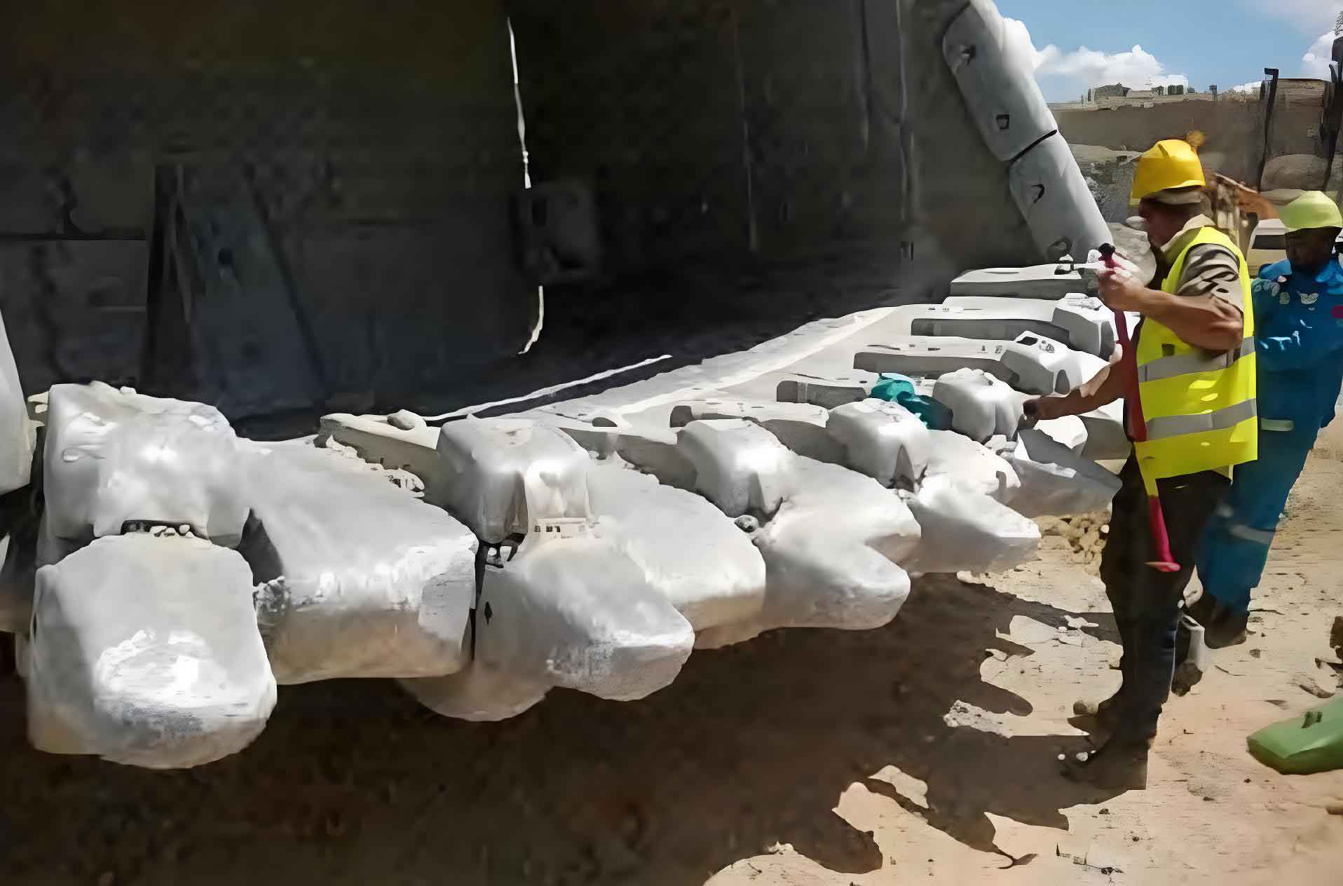
The cylinder liner studied in this research is produced by a V – process foundry. It has a contour dimension of 1180 mm × 470 mm × 340 mm and is made of a chromium – molybdenum alloy steel. The chemical composition of the alloy steel is shown in Table 1.
| Element | C | Mo | Ni | Cr | Si | Mn | Fe |
|---|---|---|---|---|---|---|---|
| Content (%) | 0.56 | 0.8 | 0.5 | 2.59 | 0.38 | 0.5 | Balance |
The alloy steel has a liquidus temperature of 1476 °C and a solidus temperature of 1117 °C. The casting process involves melting scrap steel and old liners in an intermediate frequency coreless induction furnace and adding a carburizer to adjust the carbon content. The molten steel is then poured into the mold at a pouring temperature of 1530 °C.
2.2 Simulation Analysis of the Original Casting Process
The original casting process was simulated using the ProCAST software. The simulation considered factors such as the flow field, temperature field, solid fraction, and the distribution of shrinkage porosity and cavities. The metal liquid was introduced at the end face of the liner casting, and a riser was set between the casting and the ingate to allow the metal liquid to flow into the mold cavity through the riser.
The simulation results showed that during the filling process, the metal liquid had a significant change in velocity vector when it collided with the end of the mold, which could cause the EVA film and coating layer responsible for maintaining the negative pressure in the mold to fall off, reducing the vacuum degree of the mold and potentially causing mold collapse. Additionally, during the solidification process, the riser’s position was found to be unreasonable as the feeding channel was blocked, resulting in the formation of isolated liquid phase regions in the casting and the presence of shrinkage porosity and cavities. The volume of shrinkage porosity and cavities in the casting was approximately 1155 cm³, with a weighted average porosity of about 28%. These defects were mainly concentrated in the lifting strip area of the liner, reducing the effective bearing area and causing stress concentration, which in turn decreased the mechanical properties and service life of the casting.
3. Improvement of the Casting Process
3.1 Intelligent Design of the New Casting Process
To address the issues in the original casting process, an intelligent design of the casting process was carried out using a self – developed “Intelligent Design of Casting Process (Cast Steel)” software. This software provided a one – stop service for the design of the pouring system, risers, and chills for the liner casting.
3.1.1 Pouring System Intelligent Design
The pouring system of the new casting process was designed to ensure a smooth filling process and avoid defects caused by excessive metal liquid velocity. The design followed the principle of “stability with speed” in V – process casting. The pouring time was calculated using the formula , where is a calculation coefficient, is the average wall thickness of the casting, and is the total mass of the metal liquid in the mold. Based on the characteristics of the liner casting, the values of relevant parameters were determined, and the pouring time was calculated to be approximately 75 s.
The dimensions of the pouring system components, including the ladle hole, straight runner, cross runner, and ingate, were calculated according to the pouring speed and the proportion of each component’s cross – sectional area. The ladle hole diameter was determined to be approximately 55 mm, and the cross – sectional areas of the straight runner, cross runner, and ingate were calculated as 44 cm², 48 cm², and 72 cm² respectively. The ingate was designed to be located at the parting surface of the liner casting, which effectively reduced the falling height of the metal liquid in the mold cavity and prevented inclusions caused by the scouring of the mold wall.
3.1.2 Riser Intelligent Design
The riser was designed to compensate for the solidification shrinkage of the casting. The size of the riser was calculated using an analytical method (cubic equation). First, the volume shrinkage rate of the steel liquid during solidification was calculated. The volume shrinkage rate was calculated using the formula , where is the mass fraction of carbon in the steel liquid, is the mass fraction of alloy elements, is the influence coefficient of alloy elements on the volume shrinkage rate, is the influence coefficient of pouring temperature on the volume shrinkage rate, is the pouring temperature, and is the liquidus temperature. For the chromium – molybdenum alloy steel of the liner casting, the calculated volume shrinkage rate was 5.81%.
Based on the calculated volume shrinkage rate and the volume and surface area of the casting, the equivalent diameter and height of the riser were calculated using a cubic equation. The calculated equivalent diameter of the riser was 25 cm, and the height was 37.5 cm. A cylindrical exothermic riser (HLFM – C – S300 type) was selected, with an exothermic energy of 1650 kJ/kg, an ignition temperature of 1200 °C, and an exothermic time of 240 s.
3.1.3 Determination of Riser Placement Position
The placement position of the riser was determined based on the Chvorinov thermal modulus. The Chvorinov theorem states that the thermal modulus , where is the volume of the casting and is the heat dissipation surface area of the casting. By simulating the casting process without the riser using the ProCAST software and calculating the Chvorinov thermal modulus of each part of the casting, it was found that the thermal modulus of the casting increased from the outer edge to the center, with the maximum value at the center. Therefore, the exothermic riser was placed near the center of the upper surface of the substrate.
3.2 Simulation Analysis of the New Casting Process
The new casting process was simulated using the ProCAST software. The simulation results showed that the metal liquid flowed smoothly and stably into the mold cavity during the filling process. The velocity of the metal liquid when approaching the end of the mold was relatively low, and the collision was mild, with little change in the velocity vector. During the solidification process, the metal liquid in the casting gradually solidified from the edge to the center, and the liquid phase region that was not solidified gradually contracted towards the exothermic riser. The exothermic riser continuously provided liquid compensation for the liquid shrinkage and solidification shrinkage of the casting, ensuring that the casting was always in a positive pressure state during the solidification process. The shrinkage porosity and cavities were mainly formed in the pouring system and the riser, and the liner casting had a dense structure with no significant shrinkage porosity and cavities in the casting itself.
4. Production Trial of the New Casting Process
To verify the effectiveness of the new casting process, a series of production trials were carried out. The process yield of the liner castings obtained from the production trials was all above 85%. After careful inspection, no casting defects such as shrinkage porosity, shrinkage cavities, gas holes, or slag inclusions were found in the castings. The liner castings and their representative cross – sections showed good quality and met the requirements of practical applications.
5. Conclusions
5.1 Summary of the Research Results
- The numerical simulation of the original casting process accurately predicted the distribution and size of shrinkage porosity and cavities in the liner. The causes of these defects were identified as the blockage of the feeding channel between the riser and the casting during the solidification process, resulting in the formation of an isolated liquid phase region in the center of the casting and the subsequent formation of shrinkage porosity and cavities.
- The intelligent design of the new casting process using the self – developed software effectively addressed the issues in the original casting process. The simulation and production trials showed that the new casting process eliminated the shrinkage porosity and cavities in the liner casting, improved the quality of the casting, and increased the process yield from 65% to above 85%.
5.2 Significance and Future Prospects
The improvement of the casting process of the semi – autogenous mill cylinder liner has significant economic and practical significance. It not only improves the quality and service life of the liner, reducing maintenance costs and increasing the productivity of the mining process but also provides a new approach and reference for the casting process design of similar components. In the future, further research can be carried out to optimize the casting process parameters, explore the application of new materials and technologies, and continuously improve the performance and quality of the cylinder liner to meet the increasing demands of the mining industry.
In conclusion, this research on the improvement of the casting process of the semi – autogenous mill cylinder liner has achieved good results and has important guiding significance for the development of the casting industry in the field of mining equipment.