
Abstract:
The challenges of low efficiency, high safety risks, and extended construction cycles associated with the installation of steel casting brackets for tilted dual-shaft rudder systems during the ship hull assembly stage. Taking a certain Ro-Ro ship as the research object, we analyze the precision control standards and requirements, propose a method for precision quality control of steel casting brackets pre-installed during the block construction stage, and implement this method during the construction process. The results show that this precision quality control method fully meets the operational requirements of the later ship’s main engine, significantly improves ship production and construction efficiency, shortens the shipbuilding cycle, and enhances the construction work environment.
1. Introduction
The steel casting brackets for ship dual-shaft rudder systems are traditionally installed during the hull assembly stage. This method is difficult to execute, leads to low work efficiency, has a long construction cycle, and involves high-altitude work with significant safety risks. Currently, many domestic shipyards lack experience during the initial construction of long-shaft engineering vessels, resulting in insufficient precision control awareness and multiple repair instances.
To address this, we take a certain Ro-Ro ship as the research object. Firstly, combining the precision control characteristics of dual-shaft rudder system segments, we move forward the pre-installation of steel casting brackets for dual-shaft rudder systems to the block construction stage. Secondly, starting from the splicing of steel casting brackets for shaft systems, we use three-dimensional (3D) detection technology to control the precision of each key point during pre-installation to ensure efficient and precise installation of the ship’s dual-shaft rudder system.
2. Formulation of Precision Control Plan for Steel Casting Pre-installation
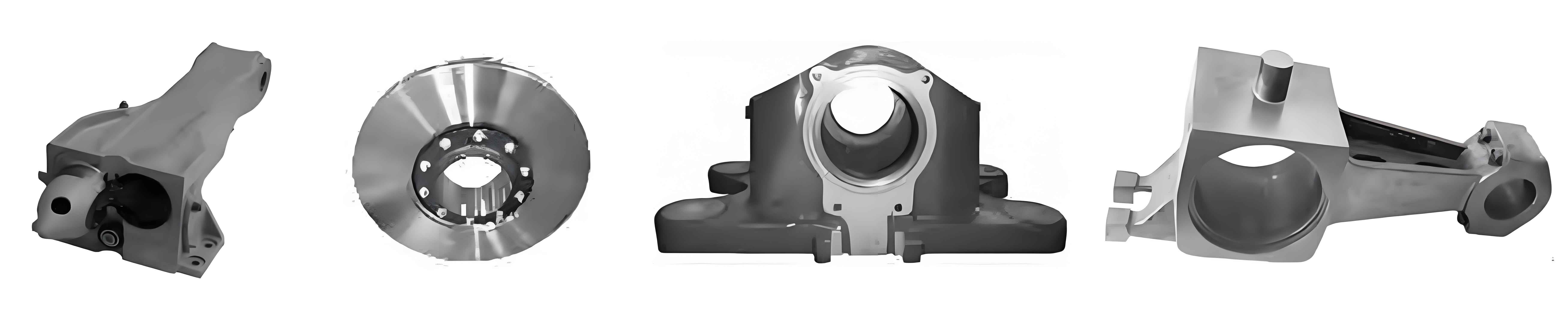
The brackets for the ship’s shaft system are all installed on the outside of the hull. There are six shaft system steel castings at the stern to fix the main engine rotating shafts and two rudder system steel castings to fix the rudder rotating shafts. The shaft system steel castings are installed on six segments: two stern castings on the ED11P/S segments, two “I”-shaped single arms on the AG02C segment, and two “V”-shaped double arms on the AG03C segment; the two rudder sleeves of the rudder system steel castings are installed on the AG01C segment.
2.1 Precision Requirements for Pre-installation
To ensure the installation precision of the dual-shaft rudder system during the assembly stage and the normal operation of the main engine shaft system, the concentricity of the steel casting shaft holes must be controlled within a 2 mm range.
2.2 Construction Environment
Due to the extremely high precision requirements for steel casting pre-installation, the construction environment must also meet high standards. To ensure that the ambient temperature during measurement remains basically the same, thereby ensuring measurement accuracy, steel casting splicing and pre-installation must be conducted indoors.
2.3 Positioning Plan
Before the pre-installation of steel castings for the shaft and rudder systems, a positioning plan must be formulated, clarifying the anti-deformation additions and positioning plan for each step of the eight steel castings during pre-installation positioning. The specifics are as follows:
(1) Positioning requirements for the two stern castings on the ED11P/S segment:
- Front-back direction: Position based on the distance from the end face of the steel casting’s first shaft hole to the end face of the segment tail, with a tolerance of 0-3 mm.
- Left-right direction: Position with the center of the shaft hole as the benchmark, with a concentricity of 0 mm and an allowable error range of ±1 mm.
- Height direction: Position with the center of the shaft hole as the benchmark, adding 3-5 mm of anti-deformation.
(2) Positioning requirements for the two “I”-shaped single arms on the AG02C segment:
- Front-back direction: Position based on the front end face of the steel casting, ensuring the single arm structure aligns with the reinforcement, and adding 4 mm of anti-deformation to the bow direction for the “I”-shaped single arm.
- Left-right direction: Position with the center of the shaft hole as the benchmark, with a concentricity of 0 mm and an allowable error range of ±1 mm.
- Height direction: Position with the center of the shaft hole as the benchmark, adding 3-5 mm of anti-deformation.
(3) Positioning requirements for the two “V”-shaped double arms on the AG03C segment:
- Front-back direction: Position based on the tail end face of the steel casting, ensuring the double arm structure aligns with the reinforcement, and adding 5 mm of anti-deformation to the stern direction for the “V”-shaped double arms.
- Left-right direction: Position with the center of the steel casting circle offset 5 mm towards the shipside.
- Height direction: Position with the center of the shaft hole as the benchmark, adding 5 mm of anti-deformation and positioning at a height of +5 mm.
(4) Positioning requirements for the two rudder sleeves on the AG01C segment:
- Front-back direction: Position based on the position of the rudder hole center on the segment, with a tolerance of 0-1 mm.
- Left-right direction: Position with the rudder hole center as the benchmark, with a tolerance of 0 mm.
- Height direction: Position based on the lower opening of the rudder sleeve as the benchmark, adding 3-5 mm of anti-deformation.
3. Implementation of Precision Control Plan for Steel Casting Segment Pre-installation
3.1 Precision Control for Steel Casting Assembly and Splicing
The “I”-shaped single arm and “V”-shaped double arm steel casting shafts are assembled from multiple steel casting sections on a horizontal iron platform jig. To ensure splicing precision quality, the following precision control requirements are imposed:
- On the platform: Draw the center benchmark for the steel casting shaft holes and the splicing positioning benchmark, then lift the steel casting onto the jig for positioning. The vertical line should ensure that the concentricity of the steel casting placement shaft holes is 1 mm and coincides with the center and splicing seam position on the platform.
- Welding: Use symmetrical welding. First, apply the bottom weld of the butt joint, then have two people perform symmetrical welding. Monitor the deformation of the support in real-time during welding, and adjust the welding sequence if deformation occurs.
- After welding: After the steel casting has completely cooled, measure the shaft hole and upper opening data to ensure that the splicing precision of the steel casting is controlled within 2 mm.
3.2 Precision Control for Stern Casting Tube Splicing
The stern casting tube is assembled from steel castings and steel pipes. The specific precision control methods are as follows:
- During assembly and positioning: Connect two sections of steel casting cylinders with one steel pipe. During positioning, add a 2-3 mm contraction allowance for each butt weld. During cylinder splicing, place a 2-3 mm high welding anti-deformation amount between the first and second butt weld positions to control weld gap contraction and deformation in the height direction during welding.
- After cylinder splicing: Move the detection points for concentricity on the inner side of the cylinder to the outer surface of the steel casting tube body, and make six detection marking points. Use a 3D total station to replace the traditional wire method for concentricity detection.
- During steel casting welding: Detect the points on the outer side of the tube body, analyze the changes in cylinder straightness, and use the straightness change data to guide adjustments to the welding sequence on site, ensuring that the concentricity of the welded stern casting tube is controlled within a 1.5 mm error range.
3.3 Precision Control for Rudder Sleeve Pre-installation
The two rudder bases on segment AG01C are situated on two curved assemblies. The accuracy of the rudder base positioning has a direct impact on the rudder sleeve positioning precision, which subsequently influences the entire rudder system positioning. Ensuring the pre-installation precision of the rudder sleeve is crucial. Therefore, during the rudder sleeve positioning phase, anti-deformation measures are implemented based on the predetermined rudder sleeve positioning plan.
To achieve this, the following steps are taken:
- Positioning and Anti-Deformation Measures:
- Baseline Establishment: After the hull structure welding of segment AG01C is completed, a three-dimensional total station instrument is used to measure the overall precision of the segment, establishing the benchmarks for the rudder sleeve positioning in terms of front-to-back, left-to-right, and up-down directions.
- Anti-Deformation Addition: Based on the pre-installation positioning scheme, anti-deformation quantities are added during the rudder sleeve positioning to counteract potential deformations during welding.
- Welding Process Monitoring and Adjustment:
- Initial Positioning: The rudder sleeves are lifted and positioned at their designated locations on the segment. Precision positioning is achieved using three-dimensional detection technology, and welding assembly proceeds once the positioning data meets the requirements.
- Welding Sequence Control: To minimize deformation, welding is carried out using clamping fixtures to secure the rudder sleeve to the strong structures, with at least 500 mm of welding length on the strong structure. Symmetrical welding methods are employed, and the welding sequence is controlled to prevent axis offset.
- Real-Time Monitoring: The center precision of the rudder sleeve is monitored in real-time using a three-dimensional total station instrument, with data detected at a frequency of once every hour. Adjustments to the welding sequence are made based on data variations to ensure precision.
- Precision Control and Verification:
- Concentricity Control: Special attention is paid to maintaining the concentricity of the rudder sleeves. During welding, measurements are taken to analyze changes in the straightness of the rudder sleeve, guiding adjustments to the welding sequence to ensure that the concentricity of the rudder sleeves is controlled within a tolerance of ±1 mm.
- Final Verification: Upon completion of welding, a final precision verification is conducted to ensure that all dimensions and concentricity requirements are met.
By following these precision control measures, the installation accuracy of the rudder sleeves is ensured, which in turn guarantees the efficient and precise installation of the entire rudder system. This approach not only meets the operational requirements of the ship’s rudder system but also enhances the overall quality and efficiency of shipbuilding.