Introduction
The steam turbine is a critical component in power generation, converting thermal energy from high-pressure steam into mechanical work. Among its various parts, the cylinder block plays a pivotal role in housing the turbine’s internal components and ensuring efficient energy conversion. Given the demanding operational conditions—high temperatures, high pressures, and rapid rotational speeds—the cylinder block must exhibit exceptional mechanical properties, including high strength, thermal stability, and resistance to creep and fatigue.
This article delves into the casting process and material preparation for a 600 MW supercritical steam turbine cylinder block. We will explore the structural and material characteristics, the challenges faced during production, and the innovative solutions employed to overcome these challenges. Additionally, we will discuss the optimization of the casting process using numerical simulation software, the preparation of high-performance heat-resistant steel, and the validation of the material’s properties through rigorous testing.
1. Structural and Material Characteristics of the Steam Turbine Cylinder Block
1.1 Structural Features
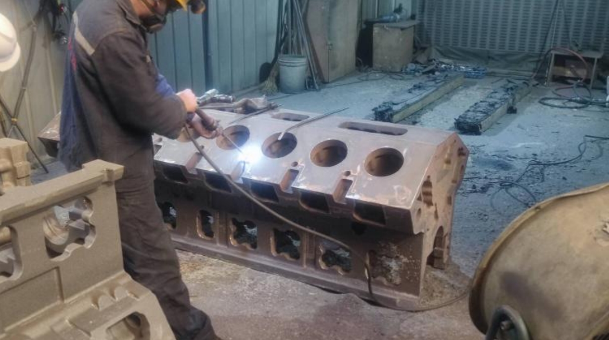
The steam turbine cylinder block is a complex, semi-circular, U-shaped structure (Figure 1). This design, while essential for housing the turbine’s internal components, presents significant challenges during casting due to its susceptibility to deformation and stress concentration.
Key structural features include:
- Mid-plane Flange: The mid-plane, which requires sealing, is typically thick and heavily bolted. This results in a significant disparity in wall thickness between the flange (up to 400 mm) and the main body (approximately 70 mm). Such variations can lead to thermal stress and cracking during solidification.
- Inlet and Outlet Pipes: The cylinder block is connected to numerous steam inlet and outlet pipes. These connections create localized stress concentrations and make sequential solidification difficult, often leading to shrinkage porosity.
- Complex Internal Cavities: The internal cavities of the cylinder block are often irregular and narrow, complicating mold production, cleaning, and inspection processes.
1.2 Material Requirements
The cylinder block is typically made from heat-resistant steel, specifically ZG12Cr9Mo1VNbN, which is designed to withstand high temperatures and pressures. The composition of this steel is critical to its performance, with elements like Chromium (Cr), Molybdenum (Mo), Vanadium (V), and Niobium (Nb) playing key roles in enhancing high-temperature strength and creep resistance.
Table 1: Composition of ZG12Cr9Mo1VNbN Heat-Resistant Steel
| Element | C | Si | Mn | P | S | Cr | Mo | V | Nb | N | Ni | Al |
|---|---|---|---|---|---|---|---|---|---|---|---|---|
| Content (%) | 0.10-0.16 | ≤0.60 | ≤0.90 | ≤0.025 | ≤0.015 | 8.00-10.0 | 0.90-1.10 | 0.15-0.25 | 0.04-0.09 | 0.03-0.06 | ≤0.60 | ≤0.020 |
1.3 Quality Requirements
The cylinder block must meet stringent quality standards, particularly in terms of non-destructive testing (NDT). Key requirements include:
- Ultrasonic Testing (UT): Critical surfaces, such as the mid-plane, must meet UT Level 1 standards, while other machined surfaces should meet UT Level 2.
- Radiographic Testing (RT): Inlet and outlet pipe connections must undergo RT to ensure the absence of defects.
- Dimensional Accuracy: The cylinder block must adhere to strict dimensional tolerances, with wall thicknesses meeting CT14 standards.
2. Casting Process Analysis
2.1 Numerical Simulation of Solidification
To optimize the casting process, numerical simulation software (MAGMA) was employed to analyze the solidification process. This involved calculating the modulus of different sections of the casting and identifying hot spots where shrinkage porosity and cracks were likely to occur.
Figure 2: Hot Spot and Modulus Analysis of the Cylinder Block Casting
The simulation revealed that the mid-plane flange was the last to solidify, making it prone to shrinkage defects. To address this, a combination of risers and chills was used to ensure sequential solidification and effective feeding.
2.2 Production Method Selection
The casting process was carried out using a multi-box molding technique, with the mid-plane oriented upwards. This approach facilitated the placement of risers and chills, ensuring effective feeding and minimizing defects.
Table 2: Comparison of Traditional and Optimized Casting Processes
| Parameter | Traditional Process | Optimized Process |
|---|---|---|
| Riser Size | Large | Small |
| Gating System | Side Gating | Bottom Gating |
| Casting Yield | 42% | 65% |
| Defect Rate | High | Low |
| Material Utilization | Low | High |
2.3 Design of Riser and Gating Systems
The original casting process used large risers and a side-gating system, which resulted in a low casting yield (42%) and increased the risk of defects. The optimized process employed smaller, more efficient risers and a bottom-gating system, improving the casting yield to 65% and reducing defects.
Figure 3: Original vs. Optimized Riser and Gating Systems
2.4 Prevention of Casting Defects
To prevent common casting defects such as shrinkage porosity and hot tearing, several design modifications were made:
- Increased Fillet Radii: Larger fillet radii were used to reduce stress concentrations and minimize the risk of cracking.
- Anti-Crack Ribs: Ribs were added to critical areas to distribute stress and prevent cracking during solidification.
- Chill Placement: Chills were strategically placed to accelerate solidification in thick sections, ensuring uniform cooling and reducing the risk of shrinkage defects.
3. Material Preparation and Heat Treatment
3.1 Development of ZG12Cr9Mo1VNbN Steel
The ZG12Cr9Mo1VNbN steel was developed to meet the demanding requirements of supercritical steam turbines. The steel’s composition was carefully controlled to optimize its high-temperature properties, with particular attention paid to the levels of Cr, Mo, V, and Nb.
Table 3: Key Alloying Elements and Their Roles in ZG12Cr9Mo1VNbN Steel
| Element | Role in Steel |
|---|---|
| Cr | Enhances high-temperature strength and corrosion resistance |
| Mo | Provides solid solution strengthening and improves creep resistance |
| V | Forms fine carbides, enhancing strength and toughness |
| Nb | Stabilizes the microstructure and improves creep resistance |
3.2 Heat Treatment Process
The heat treatment process was critical to achieving the desired microstructure and mechanical properties. The steel was subjected to a two-stage heat treatment process:
- Normalization: The steel was heated to 1050°C and held for 15 hours, followed by air cooling. This process refined the grain structure and improved toughness.
- Tempering: The steel was tempered at 740°C for 15 hours, followed by air cooling. This step relieved internal stresses and enhanced the steel’s ductility and toughness.
Table 4: Heat Treatment Parameters for ZG12Cr9Mo1VNbN Steel
| Process | Temperature (°C) | Holding Time (h) | Cooling Method |
|---|---|---|---|
| Normalization | 1050 | 15 | Air Cooling |
| Tempering | 740 | 15 | Air Cooling |
3.3 Microstructure Analysis
The microstructure of the ZG12Cr9Mo1VNbN steel was analyzed using scanning electron microscopy (SEM). The steel exhibited a uniform tempered martensitic structure, which is ideal for high-temperature applications.
Figure 4: Microstructure of ZG12Cr9Mo1VNbN Steel
4. Mechanical Properties and Performance Validation
4.1 High-Temperature Tensile Properties
The high-temperature tensile properties of the ZG12Cr9Mo1VNbN steel were evaluated at temperatures ranging from 450°C to 650°C. The results showed a gradual decrease in tensile and yield strength with increasing temperature.
Table 5: High-Temperature Tensile Properties of ZG12Cr9Mo1VNbN Steel
| Temperature (°C) | Yield Strength (MPa) | Tensile Strength (MPa) |
|---|---|---|
| 450 | 597 | 633 |
| 500 | 523 | 524 |
| 550 | 416 | 479 |
| 600 | 333 | 346 |
4.2 High-Temperature Creep Resistance
The creep resistance of the steel was evaluated through high-temperature endurance tests. The results indicated that the steel exhibited excellent creep resistance, with a gradual decrease in endurance time as the temperature and stress levels increased.
Table 6: High-Temperature Endurance Properties of ZG12Cr9Mo1VNbN Steel
| Temperature (°C) | Stress (MPa) | Endurance Time (h) |
|---|---|---|
| 550 | 210 | 109 |
| 600 | 210 | 98 |
| 600 | 140 | 167 |
| 650 | 90 | 102 |
4.3 Impact Toughness and Fracture Analysis
The impact toughness of the steel was evaluated at various temperatures, and the fracture appearance transition temperature (FATT) was determined to be -15°C. This indicates that the steel retains good toughness even at low temperatures.
Figure 5: Impact Toughness and Fracture Analysis
5. Conclusion
The casting process and material preparation for the 600 MW supercritical steam turbine cylinder block have been successfully optimized to meet the demanding requirements of modern power generation. Key achievements include:
- Optimized Casting Process: The use of numerical simulation software allowed for the effective design of risers and gating systems, resulting in a high casting yield and reduced defects.
- High-Performance Material: The development of ZG12Cr9Mo1VNbN steel, with its excellent high-temperature properties, has provided a reliable material solution for supercritical steam turbines.
- Validated Mechanical Properties: Rigorous testing confirmed the steel’s high-temperature tensile strength, creep resistance, and impact toughness, ensuring its suitability for long-term operation in demanding environments.
This comprehensive approach to casting and material preparation has set a new standard for the production of steam turbine cylinder blocks, paving the way for more efficient and reliable power generation.