1. Introduction
The diesel engine cylinder block is a crucial component in diesel engines, and its quality directly affects the performance, reliability, and durability of the engine. High – performance diesel engines require cylinder blocks with excellent mechanical properties and precise dimensions. In the process of casting high – performance diesel engine cylinder blocks, especially those made of compacted graphite cast iron, various casting defects may occur. This article focuses on the 8Y diesel engine cylinder block project, analyzes the casting defects such as leakage and shrinkage, and proposes corresponding improvement measures.
2. Project Overview of 8Y Diesel Engine Cylinder Block
2.1 Product Introduction
The 8Y diesel engine cylinder block is a product of a joint design by Shanghai New Power Automotive Technology Co., Ltd. and AVL of Austria. It is made of RuT450 compacted graphite cast iron. The maximum contour size of the cylinder block is 880 mm×560 mm×430 mm, with a main wall thickness of 4.5 mm and a maximum wall thickness of 61 mm. The casting quality is 203 kg. As shown in Figure 1, the product includes six cylinder bores, a crankshaft chamber, an oil – gas chamber, a oil – cooler chamber, a gear chamber, and intake and exhaust surfaces. It is mainly applied in heavy – duty trucks, buses, and construction machinery.
[Insert Figure 1: 8Y cylinder block casting 3D diagram]
2.2 Technical Requirements
The technical requirements for the 8Y diesel engine cylinder block mainly include chemical composition, mechanical properties, dimensional tolerances, and surface quality. The chemical composition requirements are shown in Table 1.
| Element | C | Si | Mn | P | S | Cu | Sn |
|---|---|---|---|---|---|---|---|
| Mass Fraction (%) | 3.65 – 3.85 | 1.8 – 2.2 | 0.3 – 0.5 | ≤0.02 | 0.010 – 0.018 | 0.8 – 0.9 | 0.08 – 0.09 |
| Table 1: Chemical Composition of the Material |
The mechanical properties requirements are presented in Table 2.
| Heat Treatment | Tensile Strength (MPa) | Surface Hardness (HB) |
|---|---|---|
| Stress – relief Annealing | ≥450 | 190 – 250 |
| Table 2: Mechanical Property Requirements |
The casting dimensional tolerance is in accordance with CT8 grade, and the surface roughness is ≤Ra25. The casting surface should be flat, smooth, with a clear contour, and free of defects such as sand – sticking, sand – inclusion, and extra – material defects.
3. Casting Process Scheme
3.1 Production Process
The production of the 8Y cylinder block in the company adopts the following processes: triethylamine cold – box core – making, medium – frequency electric furnace melting, OCC wire – feeding vermicularization treatment, HWS static – pressure molding line molding, and continuous annealing furnace heat treatment. The size of the sand box is 1450 mm×1100 mm×420 mm/420 mm.
3.2 Casting Process
The casting process uses a horizontal pouring and side – injection method, with one casting per box. As shown in Figure 2 and Figure 3, the pouring cup is located in the middle of the upper sand mold. Molten iron enters the mold through the sprue, runner, sub – runner, and ingate, and finally flows into the product part of the mold. The pouring temperature is (1430 ± 10)°C, the pouring time is (22 ± 3)s, and the total pouring mass per box is 300 kg.
[Insert Figure 2: Casting process diagram (front view)]
[Insert Figure 3: Casting process diagram (right view)]
4. Problem Description and Cause Analysis
4.1 Leakage Defect
4.1.1 Defect Description
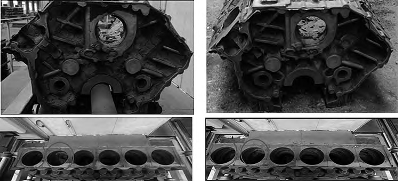
The leakage defect is located at the flange of the gear chamber on the rear end face of the cylinder block. The appearance of the casting is incomplete, and the defect is in the shape of an empty shell, as shown in Figure 4.
[Insert Figure 4: Physical diagram of leakage defect]
4.1.2 Cause Analysis
Compacted graphite cast iron has stronger fluidity than gray cast iron. The gear chamber part of the product is far from the pouring cup, and the defect location is the highest point during pouring, making it easy to form defects such as misruns or leakage. Through process tracking and analysis, it is found that there is an eccentric problem after core – setting, resulting in a large local gap at the core – fitting part. During pouring, the molten iron leaks from the gap, which is the main cause of the leakage defect.
4.2 Shrinkage Defect
4.2.1 Defect Description
The shrinkage defect is located at the thick section between the two cylinder bores of the cylinder block, presenting as concentrated small holes. The defect area is significantly different from the normal cross – section, as shown in Figure 5.
[Insert Figure 5: Cross – sectional view of shrinkage defect]
4.2.2 Cause Analysis
Compacted graphite cast iron solidifies in a “mushy” manner. When the thick hot – spot solidifies, if there is no molten iron supplement, shrinkage defects are likely to form. In addition, the original pouring temperature of (1430 ± 10)°C is on the high side, and the carbon equivalent (CE = 4.25 – 4.58) is on the low side, which also creates conditions for the formation of shrinkage defects.
5. Improvement Measures
5.1 Process Optimization Scheme for Solving Leakage Defects
5.1.1 Calibrating the Core – setting Fixture
By adjusting the parameters of the core – setting equipment and the positioning points of the core – setting fixture, the core – setting position is calibrated to ensure that the sand core can be accurately placed in the mold cavity.
5.1.2 Blocking the Leakage Risk Points between the Sand Mold and the Sand Core
Fire – resistant gaskets are placed at the leakage risk points of the core to block the leakage path of the molten iron, as shown in Figure 6.
[Insert Figure 6: Position diagram of sand core in sand mold]
5.2 Process Optimization Scheme for Solving Shrinkage Defects
5.2.1 Lowering the Pouring Temperature
Lowering the pouring temperature is beneficial to reducing the shrinkage tendency of compacted graphite cast iron. The original pouring temperature of the product is (1430 ± 10)°C, and after adjustment, it is (1410 ± 10)°C.
5.2.2 Adjusting the Content of Trace Elements in Molten Iron
The carbon equivalent (CE) is increased by increasing the content of C and Si elements. The C element content in the original molten iron is increased from 3.60% – 3.80% to 3.78% – 3.85%, the Si element content is increased from 1.85% – 1.90% to 2.10% – 2.20%, and at the same time, the Mn element content is decreased from 0.40% – 0.50% to 0.30% – 0.40%, as shown in Table 3.
| Scheme Implementation | Pouring Temperature T (°C) | Material Chemical Composition (wt%) | ||
|---|---|---|---|---|
| C | Si | Mn | ||
| Before Implementation | 1430 ± 10 | 3.65 – 3.80 | 1.85 – 1.90 | 0.40 – 0.50 |
| After Implementation | 1410 ± 10 | 3.78 – 3.85 | 2.10 – 2.20 | 0.30 – 0.40 |
| Table 3: Comparison of Melting Processes before and after Measure Implementation |
6. Implementation Effect
6.1 Leakage Defect
Before the process optimization, the leakage defect rate was 41.67%. After implementing the two measures of calibrating the core – setting fixture and blocking the leakage points, the leakage defect rate dropped to 0. The experimental results are shown in Table 4, and the defect improvement effect is shown in Figure 7.
| Whether Measures are Taken | Process Measure Content | Test Quantity (pieces) | Leakage (pieces) | Defect Rate (%) |
|---|---|---|---|---|
| No | None | 24 | 10 | 41.67 |
| Yes | Only calibrate the core – setting fixture | 24 | 6 | 25.00 |
| Yes | Only block the leakage points | 24 | 1 | 4.17 |
| Yes | Implement both of the above measures | 24 | 0 | 0.00 |
| Table 4: Statistics of Leakage Defect Rates before and after Measure Implementation | ||||
| [Insert Figure 7: Physical diagram of leakage improvement effect] |
6.2 Shrinkage Defect
Before the process optimization, the shrinkage defect rate was 37.50%. After implementing the two measures of lowering the wire – feeding treatment temperature and adjusting the trace elements in the molten iron, the shrinkage defect rate of the sampled inspection dropped to 0%. The experimental results are shown in Table 5, and the defect improvement effect is shown in Figure 8.
| Whether Measures are Taken | Process Measure Content | Test Quantity (pieces) | Sampled and Sectioned Quantity (pieces) | Shrinkage (pieces) | Defect Rate (%) |
|---|---|---|---|---|---|
| No | None | 24 | 8 | 3 | 37.50 |
| Yes | Only lower the wire – feeding treatment temperature | 24 | 8 | 1 | 12.50 |
| Yes | Only adjust the original molten iron trace elements | 24 | 8 | 1 | 12.50 |
| Yes | Implement both of the above measures | 24 | 8 | 0 | 0.00 |
| Table 5: Statistics of Shrinkage Defect Rates before and after Measure Implementation | |||||
| [Insert Figure 8: Physical cross – sectional view of shrinkage improvement effect] |
7. Conclusion
7.1 Solutions for Leakage Defects
Calibrating the core – setting fixture and blocking the leakage risk points between the sand mold and the sand core are effective in solving the casting leakage defects. A large number of production verifications have been carried out in the company, and this solution can be used as a reference for solving similar problems in production.
7.2 Solutions for Shrinkage Defects
There are various solutions for shrinkage defects in compacted graphite cast iron. This article presents two methods starting from the melting process. For common shrinkage defects, it is more inclined to design heat – generating and insulating risers and chills. However, when the defect location is not convenient for conventional operations, the methods in this article can be referred to, considering reducing the shrinkage tendency of molten iron.
7.3 Characteristics of Compacted Graphite Cast Iron
Compacted graphite cast iron has good comprehensive properties, with strength and toughness close to those of nodular cast iron, and machinability and casting performance close to those of gray cast iron, especially its excellent thermal fatigue resistance. However, in actual production, stably casting compacted graphite cast iron products in large quantities is much more difficult than casting gray cast iron and nodular cast iron products, and every link needs to be carefully considered.
8. Future Research Directions
Although the casting defects of the 8Y diesel engine cylinder block have been effectively solved in this study, there are still many aspects that can be further explored. For example, further research on the influence of different molding materials on the casting quality of compacted graphite cast iron cylinder blocks. Different molding sands may have different effects on the surface quality and internal structure of castings. In addition, the optimization of the heat treatment process can also be studied. A more reasonable heat treatment process may further improve the mechanical properties of cylinder blocks. Moreover, with the development of new casting technologies, such as 3D printing – assisted casting technology, exploring its application in the production of diesel engine cylinder blocks may bring new breakthroughs in casting quality and production efficiency.
9. Conclusion
The research on the casting defects of high – performance diesel engine cylinder blocks is of great significance for improving the quality of diesel engines. By analyzing the leakage and shrinkage defects in the 8Y diesel engine cylinder block project, corresponding improvement measures have been proposed and achieved good results. In the future, continuous research and innovation are needed to further improve the casting quality of diesel engine cylinder blocks and meet the increasingly high – performance requirements of diesel engines.