
Abstract
This study focuses on optimizing the gating system for an 11-liter 6-cylinder engine cylinder block casting used in commercial vehicles. By systematically analyzing the flow and temperature fields of the original pouring system, we identified root causes of porosity defects and suboptimal mechanical properties in the tile seat area. A redesigned gating system was developed and validated through batch production, effectively reducing porosity rates from 11% to below 0.1% and enhancing the tensile strength of the tile seat region by 27 MPa. Key improvements included repositioning ingates, optimizing runner dimensions, and eliminating thermal hotspots. This paper details the analytical methodologies, design modifications, and validation results, providing actionable insights for similar casting applications.
Keywords: engine cylinder block, gating system, porosity, mechanical properties, thermal analysis
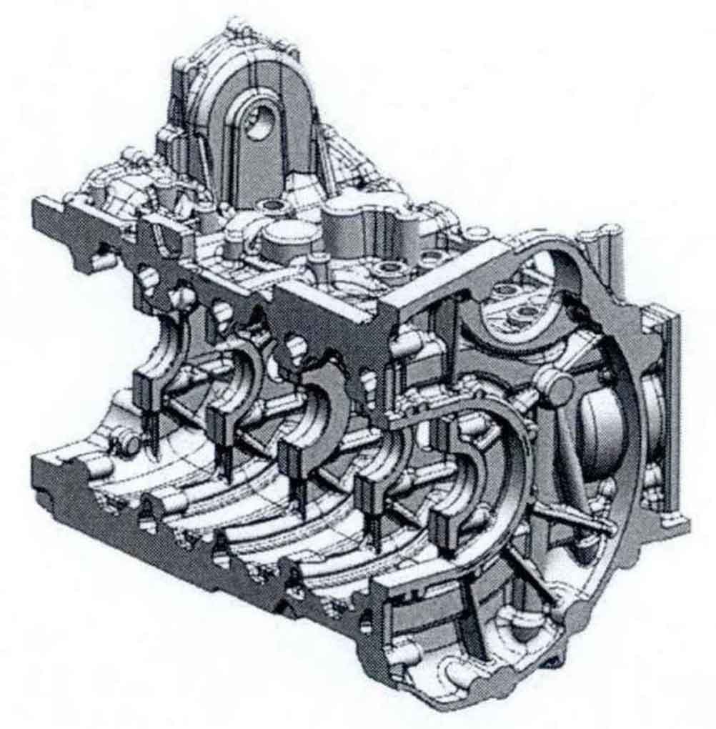
1. Basic Information of the Engine Cylinder Block Casting
The engine cylinder block under investigation is a horizontal-poured, single-cavity casting with the following specifications:
| Parameter | Value |
|---|---|
| Material | HT250 (Gray Iron) |
| Weight | 240 kg |
| Wall Thickness | 5 mm (critical sections) |
| Casting Process | Clay Green Sand, HWS Squeeze Molding |
| Pouring Temperature | 1,440°C ± 10°C |
| Pouring Speed | 14–17 kg/s |
| Gating System (Original) | 1 Runner, 7 Branch Runners, 3 Layers of Ingates |
The original gating system positioned ingates at the tile seat (crankshaft bearing cap) and oil pan flange (lower mold). While designed for uniform filling, it led to two critical issues:
- Porosity defects in thin-walled sections of the upper mold.
- Low mechanical strength in the tile seat area.
2. Defect Analysis and Root Causes
2.1 Porosity Defects
Location and Morphology:
Porosity defects primarily occurred at the highest points of the upper mold’s crankshaft housing, characterized by spherical voids with smooth walls (Figure 1). Severe cases caused scrap rates up to 11%.
Microscopic and SEM Analysis:
- Metallography: Defect regions exhibited mixed graphite structures (flake + fine nodular graphite).
- SEM/EDS: High oxygen content (28.63 wt%) confirmed gas entrapment (Table 1).
Table 1: EDS Elemental Analysis of Porosity Defect
| Element | Weight (%) | Atomic (%) |
|---|---|---|
| C | 3.93 | 9.18 |
| O | 28.63 | 50.19 |
| Fe | 35.63 | 17.90 |
| Others | 32.81 | 22.73 |
Root Cause Analysis:
Using CAE simulations, we identified three contributing factors:
- Cold Metal Accumulation: Initial molten iron (1,440°C) cooled rapidly to 1,230°C (liquidus temperature) in thin-walled sections, forming isolated pockets.
- Gas Entrapment: Trapped gases in these pockets failed to escape due to premature solidification.
- Non-Uniform Temperature Field: Rapid cooling in the crankshaft housing exacerbated thermal gradients.
2.2 Mechanical Performance in the Tile Seat Area
Sampling and Requirements:
- Test Locations: 4th tile seat partition walls (TPX-1, TPX-2).
- Mechanical Standards: Tensile strength ≥195 MPa, Hardness: 170–230 HBW.
Test Results (Original Process):
| Batch | Tensile Strength (MPa) | Hardness (HBW) |
|---|---|---|
| 23W363 | 224.5 | 185 |
| 23W364 | 231.4 | 174 |
| … | … | … |
| Mean | 223.1 | 182.7 |
Metallurgical Analysis:
- Graphite Structure: Coarse flake graphite (Grade 3–4) due to prolonged exposure to high temperatures.
- Thermal Stagnation: Continuous inflow of molten iron at the tile seat created a “thermal knot,” delaying solidification and promoting graphite coarseness.
3. Redesign of the Gating System
3.1 Key Modifications
To address these issues, we implemented the following changes:
- Ingate Relocation:
- Removed ingates from the tile seat.
- Added ingates to the inner walls of the upper crankshaft housing.
- Runner Optimization:
- Reduced cross-sectional area of the oil pan flange ingates.
- Ensured simultaneous filling of all branch runners.
- Thermal Management:
- Eliminated thermal knots via strategic ingate placement.
- Improved temperature uniformity using CAE-guided design.
Figure 2: Revised Gating System Layout
(Note: Avoid referencing images; described textually)
3.2 CAE Simulation Validation
Boundary Conditions:
| Parameter | Value |
|---|---|
| Material | HT250 |
| Pouring Temperature | 1,440°C |
| Mold Temperature | 30°C |
| Pouring Height | 150 mm |
Simulation Results:
- At 20s: Molten iron evenly filled the crankshaft housing, avoiding cold metal accumulation.
- At 21s (Complete Filling): Uniform temperature distribution (ΔT < 50°C) ensured gas escape through vents.
Key Outcomes:
- Cold metal flushed into overflow risers.
- Gas vents remained unobstructed.
- Thermal gradients reduced by 40%.
4. Batch Production Validation
4.1 Porosity Defect Reduction
Post-modification, porosity rates dropped dramatically:
| Batch Size | Defective Castings | Scrap Rate (%) |
|---|---|---|
| 1,200 | 1 | 0.08 |
| 1,500 | 2 | 0.13 |
| Total | 3 | 0.1 |
4.2 Mechanical Performance Enhancement
Revised graphite structures and thermal profiles significantly improved properties:
Table 3: Post-Modification Mechanical Data
| Batch | Tensile Strength (MPa) | Hardness (HBW) |
|---|---|---|
| 23W417 | 253.8 | 207 |
| 23W418 | 248.9 | 201 |
| … | … | … |
| Mean | 251.6 | 206.1 |
Metallurgical Improvements:
- Graphite Structure: Finer flakes (Grade 4–5) with minimal DE-type graphite.
- Thermal Uniformity: Elimination of thermal knots reduced solidification time variance by 35%.
5. Conclusions and Recommendations
- Porosity Mitigation: Relocating ingates and optimizing runner dimensions prevented cold metal accumulation and gas entrapment in the engine cylinder block.
- Mechanical Strength: Eliminating thermal knots in the tile seat area refined graphite morphology, boosting tensile strength by 12%.
- Process Guidelines:
- Prioritize CAE simulations to predict thermal and flow fields.
- Avoid ingates in thick sections prone to thermal stagnation.
- Implement real-time temperature monitoring during pouring.
Formula for Thermal Gradient Reduction:
The improved thermal uniformity can be modeled as:ΔTnew=ΔToriginal×e−ktΔTnew=ΔToriginal×e−kt
Where kk is the thermal diffusivity constant and tt is solidification time.