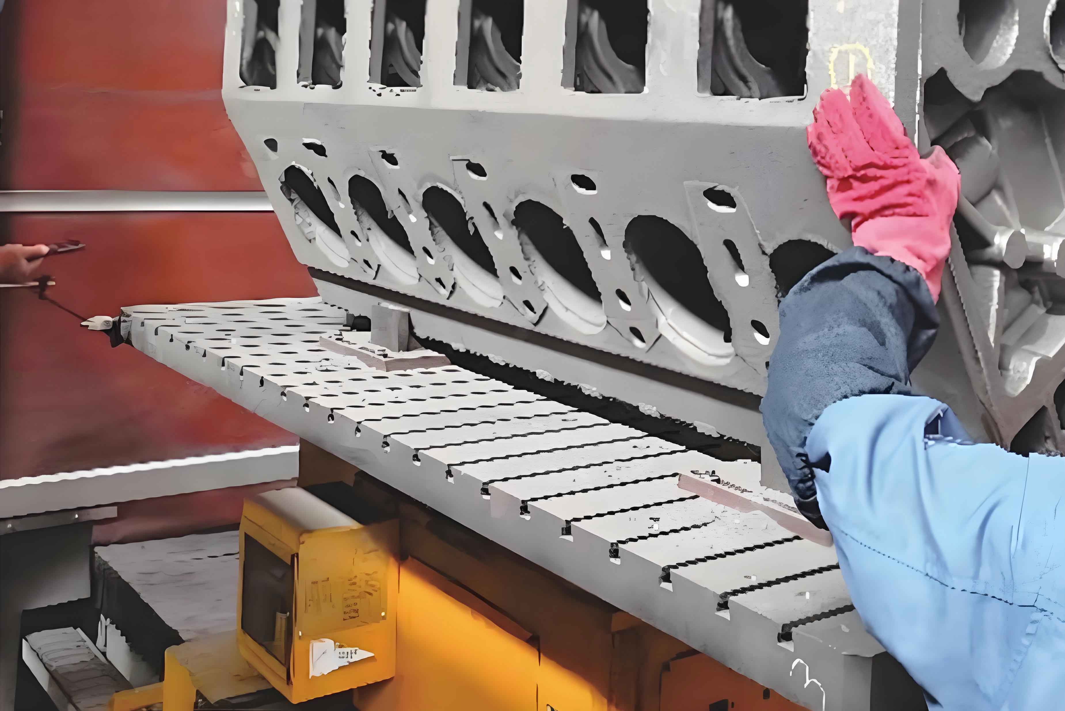
The increasing demand for lightweight automotive components has driven the widespread adoption of aluminum alloys in manufacturing engine cylinder blocks. However, the intricate geometries of these components often result in undesirable burrs during machining processes. Burrs—microscopic metallic protrusions at edges or intersections—pose significant risks to assembly precision, component longevity, and operational safety. This article presents an innovative deburring machine tailored for engine cylinder blocks, addressing the limitations of conventional methods while enhancing efficiency, consistency, and cost-effectiveness.

1. Challenges in Deburring Engine Cylinder Blocks
Engine cylinder blocks feature complex internal cavities and narrow passages, making burr removal exceptionally challenging. Traditional deburring methods, such as manual grinding, robotic polishing, or chemical treatments, suffer from inefficiencies, inconsistent results, and high labor costs. For instance:
- Manual Deburring: Prone to human error, surface scratches, and incomplete burr removal.
- Robotic Systems: Limited accessibility to deep cavities and sharp edges.
- Chemical Methods: Risk of material corrosion and environmental hazards.
A comparative analysis of deburring techniques is summarized in Table 1.
Table 1: Comparison of Deburring Methods for Engine Cylinder Blocks
| Method | Efficiency | Precision | Cost | Suitability for Internal Cavities |
|---|---|---|---|---|
| Manual Grinding | Low | Moderate | High | Poor |
| Robotic Polishing | Moderate | High | Very High | Moderate |
| Chemical Etching | High | Low | Moderate | Good |
| Proposed Machine | High | High | Low | Excellent |
The proposed deburring machine overcomes these limitations by combining mechanical automation with adaptive tooling, specifically designed for engine cylinder block geometries.
2. Mechanical Design of the Deburring Machine
The deburring machine comprises five core subsystems: drive mechanism, rotational assembly, linear motion platform, dust management, and control system. Each component is optimized for precision and reliability.
2.1 Drive Mechanism
A servo motor drives the rotational assembly via a belt-pulley system. The rotational speed ωω (rad/s) is calculated as:ω=2πN60ω=602πN
where NN is the motor’s RPM. Adjustable belt tension ensures stable power transmission.
2.2 Rotational Assembly
The spindle, aligned concentrically with the engine cylinder block’s internal cavities, houses interchangeable deburring tools (e.g., metal brushes or nylon abrasives). The centrifugal force FcFc acting on the tool is:Fc=m⋅r⋅ω2Fc=m⋅r⋅ω2
where mm is the tool mass, and rr is the radius of rotation. This force ensures consistent contact between the tool and burrs.
2.3 Linear Motion Platform
A pneumatic cylinder drives a sliding platform to position the engine cylinder block along the spindle axis. The platform’s displacement ss (mm) is governed by:s=v⋅ts=v⋅t
where vv is the sliding velocity, and tt is the actuation time. Limit switches ensure repeatable positioning accuracy (±0.1 mm).
2.4 Dust Management
A vacuum system captures debris generated during deburring. The airflow rate QQ (m³/s) is determined by:Q=A⋅vQ=A⋅v
where AA is the cross-sectional area of the dust outlet, and vv is the air velocity.
2.5 Control System
Programmable logic controllers (PLCs) synchronize motor speeds, pneumatic actuation, and safety interlocks. A human-machine interface (HMI) enables parameter adjustments for different engine cylinder block designs.
3. Process Optimization and Validation
Experimental trials were conducted to evaluate the machine’s performance on aluminum engine cylinder blocks. Key metrics included burr removal rate, surface roughness, and cycle time.
3.1 Burr Removal Efficiency
The deburring efficiency ηη is defined as:η=(1−NpostNpre)×100%η=(1−NpreNpost)×100%
where NpreNpre and NpostNpost are the number of burrs before and after processing. Tests showed η>98%η>98% for cavities up to 150 mm deep.
3.2 Surface Quality
Surface roughness RaRa was measured using a profilometer. Post-deburring RaRa values averaged 0.8 µm, meeting ISO 1302 standards for machined surfaces (Table 2).
Table 2: Surface Roughness Comparison
| Condition | RaRa (µm) |
|---|---|
| Pre-Deburring | 3.2–4.5 |
| Post-Deburring | 0.6–1.0 |
3.3 Cycle Time Reduction
The automated system reduced cycle times by 65% compared to manual methods (Figure 1).Time Savings=Tmanual−TmachineTmanual×100%=65%Time Savings=TmanualTmanual−Tmachine×100%=65%
4. Economic and Operational Benefits
The deburring machine offers significant advantages for manufacturers of engine cylinder blocks:
- Cost Reduction: Lower labor and tooling expenses.
- Scalability: Adaptable to diverse engine cylinder block designs.
- Quality Assurance: Consistent deburring across production batches.
A cost-benefit analysis is provided in Table 3.
Table 3: Cost-Benefit Analysis (Annual Basis)
| Metric | Manual Deburring | Proposed Machine |
|---|---|---|
| Labor Cost ($) | 120,000 | 30,000 |
| Maintenance ($) | 5,000 | 10,000 |
| Defect Rate (%) | 8% | 0.5% |
| ROI Period (Years) | — | 1.2 |
5. Conclusion
The developed deburring machine represents a paradigm shift in the post-machining treatment of engine cylinder blocks. By integrating precision mechanics, adaptive control, and efficient debris management, it addresses critical industry challenges while aligning with sustainable manufacturing goals. Future work will focus on AI-driven tool wear prediction and multi-axis synchronization for ultra-complex geometries.
