
As a leading manufacturer in the engine casting industry, our company has consistently prioritized advancements in core technologies to meet the escalating demands of heavy-duty engine cylinder block production. Over recent years, we have achieved a market share exceeding 30%, with annual output surpassing 1 million units. These engine cylinder blocks are integral to heavy-duty trucks, buses, urban transit systems, and specialized machinery. However, the traditional cleaning processes for these components—particularly for complex geometries like high-Lion-structure cylinder blocks—have posed significant challenges due to labor-intensive workflows, hazardous environments, and inconsistent quality outcomes. This article details our groundbreaking approach to achieving full-process automation in engine cylinder block cleaning, combining advanced robotics, intelligent systems, and optimized casting design.
1. Technical Challenges in Engine Cylinder Block Cleaning
Modern engine cylinder blocks demand exceptional performance characteristics:
- Material Properties: HT300-RT450 cast iron with tensile strength σb≥300 MPa and hardness ≥450 HBW.
- Structural Complexity: Integrated gear chambers, crankcases, and dry/wet hybrid liners with wall thicknesses of 4–5.5 mm.
- Quality Metrics: Surface roughness Ra≤6.3 μm, internal cavity cleanliness ≤50 mg/kg, and dimensional tolerances of ±0.2 mm.
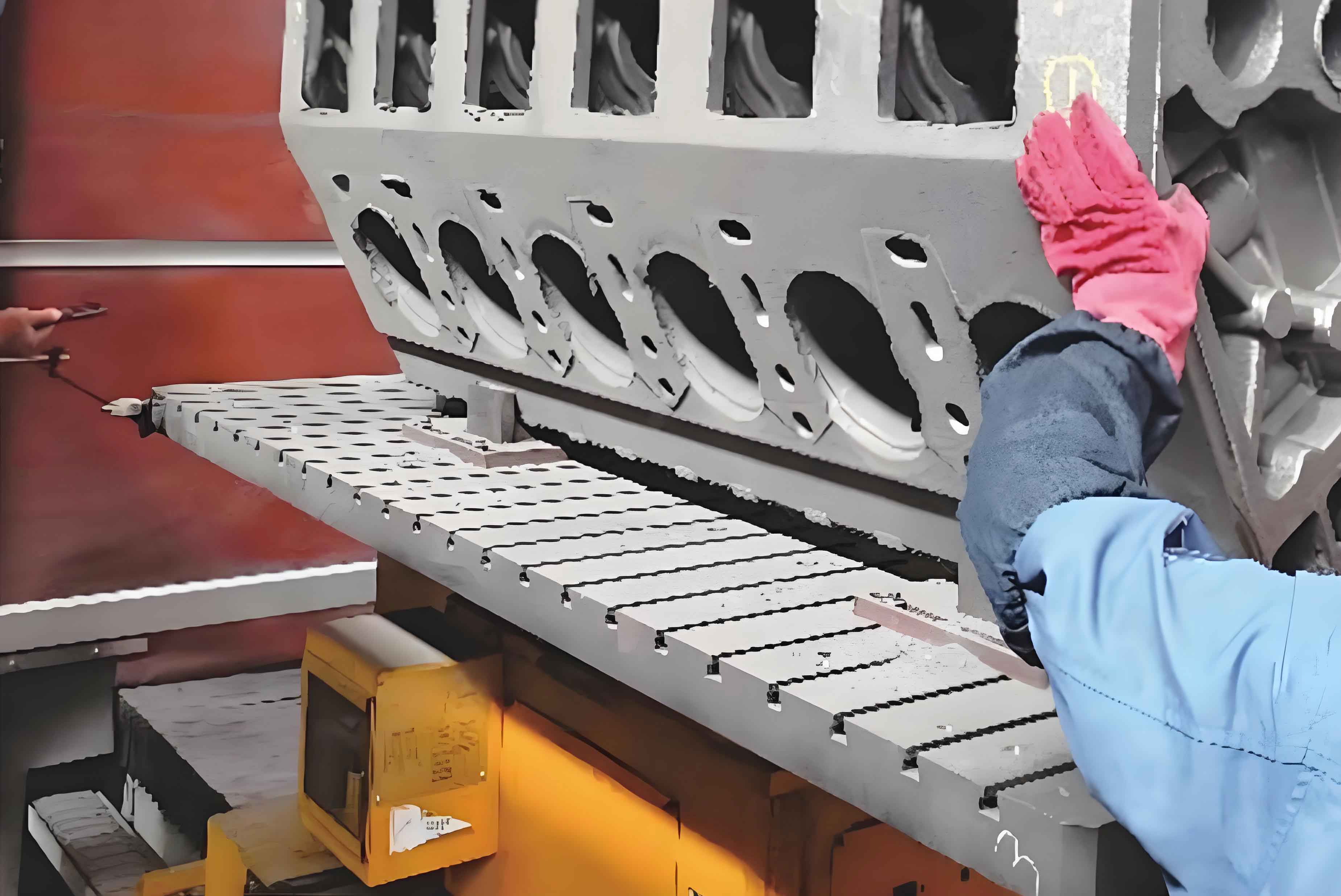
Traditional cleaning workflows relied on manual operations for:
- Deburring and gate removal
- Core shakeout
- Surface grinding and polishing
- Internal cavity desanding
- Final inspection
These processes exposed workers to airborne particulates (PM2.5 concentrations > 500 µg/m³), repetitive stress injuries, and high accident rates (industry average: 12 incidents per 200,000 work hours).
2. Automated Cleaning System Architecture
Our redesigned cleaning process integrates four modular subsystems:
| Subsystem | Key Components | Technical Parameters |
|---|---|---|
| Automated Transfer | 6-axis robots + 3D vision guidance | Positioning accuracy: ±0.1 mm; Cycle time: 90 s |
| Flexible Grinding | CNC abrasive units + AI path planning | Spindle power: 15 kW; Torque: 120 Nm |
| Internal Cavity Cleaning | Dual-robot shot blasting + Adaptive nozzles | Media flow rate: 300 kg/h; Pressure: 0.6 MPa |
| Quality Assurance | Hyperspectral imaging + ML defect detection | Resolution: 5 µm; Throughput: 40 components/hour |
2.1 Robotic Material Handling
The foundation of automation lies in reliable workpiece positioning. For engine cylinder blocks, we derived clamping force requirements using:Fc=n⋅cosθμ⋅m⋅g
Where:
- Fc = Clamping force per contact (N)
- μ = Friction coefficient (0.25 for cast iron)
- m = Component mass (270–400 kg)
- g = Gravitational acceleration (9.81 m/s²)
- n = Number of clamping points (4–6)
- θ = Angular deviation from vertical (≤5°)
Vision-assisted robots now achieve 99.7% successful pickup rates across 32 product variants, reducing manual intervention by 85%.
3. Process Optimization Strategies
3.1 Gating System Redesign
Original three-tier gating systems caused turbulence and excessive residual gates. We implemented:
- Two-stage vertical gating with optimized cross-sections:
- Sprue diameter: D=3πv4Q
Where Q = flow rate (0.8 kg/s), v = fill velocity (1.2 m/s)
- Sprue diameter: D=3πv4Q
- Thin-slice overflow vents (≤4 mm thickness) reduced post-casting cleanup by 60%
3.2 Core Shakeout Automation
Traditional vibratory methods damaged delicate engine cylinder block features. Our solution combines:
- Frequency-modulated vibration:
f=2π1mk
Tuned to 18–22 Hz for optimal sand removal without geometric distortion - Pneumatic core extraction with <0.1 mm positional repeatability
4. Intelligent Surface Finishing
4.1 Adaptive Grinding Algorithms
For variable engine cylinder block geometries, we developed:
- Real-time force feedback:
Fgrind=kp⋅e+ki∫edt+kddtde
PID-controlled to maintain optimal 80–120 N grinding force - Toolpath optimization using genetic algorithms reduced cycle times by 22%
4.2 Laser-Guided Defect Removal
Critical surfaces (e.g., cylinder bore seats) undergo:
- Topographic mapping via confocal lasers (λ=635 nm)
- Selective material ablation with pulsed YAG lasers (E=50 mJ/pulse)
5. Internal Cavity Cleaning Breakthroughs
5.1 Multi-Stage Desanding
Engine cylinder block coolant/oil passages require:
- Preconditioning: Rotary impact desanding (energy density: 15 J/cm²)
- High-Pressure Jet Cleaning:
P=2A2ρQ2
Where P = jet pressure (25 MPa), ρ = media density (1,250 kg/m³), Q = flow rate (0.01 m³/s) - Residual Particle Analysis: XRF spectroscopy ensures Fe/Si ratio <0.03%
5.2 Self-Learning Inspection Systems
Deep neural networks trained on 50,000+ engine cylinder block images achieve:
- 98.6% defect detection accuracy
- <0.5% false positive rate
6. Performance Metrics and Outcomes
| Parameter | Traditional Process | Automated System | Improvement |
|---|---|---|---|
| Cycle Time | 8.5 hours | 2.2 hours | 74% ↓ |
| Labor Intensity | 12 operators/shift | 3 technicians/shift | 75% ↓ |
| Surface Consistency (σ) | 4.7 µm | 1.2 µm | 74% ↓ |
| Energy Consumption | 58 kWh/unit | 32 kWh/unit | 45% ↓ |
These advancements have enabled our engine cylinder blocks to meet Euro VII/Tier 4 Final emissions standards while reducing per-unit cleaning costs by 63%.
7. Future Directions
Ongoing R&D focuses on:
- Quantum dot tagging for real-time engine cylinder block traceability
- Self-healing coatings applied during final polishing (α-Al₂O₃ nanocomposites)
- Digital twin integration for predictive maintenance (MTBF > 10,000 hours)
By persistently innovating at the intersection of casting technology and Industry 4.0 automation, we are redefining quality benchmarks for next-generation engine cylinder blocks while establishing safer, more sustainable manufacturing ecosystems.