1. Introduction
Frozen sand mold casting technology has emerged as a promising alternative to traditional casting techniques, primarily due to its remarkable advantages such as being environmentally friendly and recyclable. This technology involves creating sand molds using pure water as a binder. The process begins with mixing an appropriate amount of water into fine sand, which is then frozen at low temperatures to form a frozen sand blank. Subsequently, the frozen sand mold is machined through subtractive manufacturing principles. This not only reduces dust during the mold – making process but also allows for the easy 溃散 of the sand mold after casting, emits no pungent odors, and enables the reuse of the sand, facilitating the rapid production of single – piece, small – batch, and complex metal parts [1 – 3].
However, a significant challenge lies in the handling of frozen sand mold thin – walled components after they are processed by green casting forming machine tools. At low temperatures, frozen sand molds are brittle, and ensuring stable clamping without causing damage is crucial. This has become the focal point of research in this area.
Previous studies related to frozen sand molds have mainly focused on aspects such as the development of digital mold – free composite casting equipment and intelligent green casting factories [4], the influence of freezing temperature and water content on the tensile strength and air permeability of frozen sand molds [5], the optimization of CNC machining paths for complex casting sand molds [6], and the analysis of the evolution of phase fields and temperature fields in frozen sand molds with different pore structures [7]. Additionally, numerous scholars have investigated materials with similar mechanical properties to frozen sand molds, like 冻土 (frozen soil), frozen sandstone, and concrete, exploring the impact of various factors on their mechanical properties such as triaxial (uniaxial) compressive strength, stress – strain curves, and deformation parameters [9 – 16]. Nevertheless, there is a lack of research on optimizing the elastic deformation clamping parameters for safely and stably clamping frozen sand molds without damage. This study aims to fill this gap by conducting in – depth research through numerical simulations.
2. Experimental Parameters and Clamping Scheme
2.1 Compressive Strength Determination
At – 20°C, compressive strength tests were carried out on frozen sand molds made of different water contents and various sand mold materials. The sand mold materials included 100 – mesh silica sand, 100 – mesh zircon sand, and 100 – mesh chromite sand. As depicted in Figure 1, with the increase in water content, the compressive strength of the frozen sand mold gradually increases. For example, when the water content (mass fraction) of silica sand is 4%, 6%, and 8%, the compressive strengths are 2.187 MPa, 2.448 MPa, and 2.551 MPa respectively.
| Sand Mold Material | Water Content (Mass Fraction) | Compressive Strength (MPa) |
|---|---|---|
| Silica Sand | 4% | 2.187 |
| Silica Sand | 6% | 2.448 |
| Silica Sand | 8% | 2.551 |
| Zircon Sand | 4% | 2.429 |
| Chromite Sand | 4% | – |
Figure 1: Compressive strength of sand molds with different frozen sand molds under different water contents
2.2 Friction Coefficient Determination
During the handling of frozen sand molds by the clamping device, the outer surface of the frozen sand mold comes into direct contact with the fixture. Friction coefficient measurements were conducted between several materials with good low – temperature performance and frozen sand molds made of different water contents and materials, as shown in Figure 2 and Figure 3. When the water content (mass fraction) of silica sand is 6%, the friction coefficients with rubber plates, steel plates, and polyurethane plates are 0.563, 0.322, and 0.397 respectively.
| Sand Mold Material | Water Content (Mass Fraction) | Contact Material | Friction Coefficient |
|---|---|---|---|
| Silica Sand | 6% | Rubber Plate | 0.563 |
| Silica Sand | 6% | Steel Plate | 0.322 |
| Silica Sand | 6% | Polyurethane Plate | 0.397 |
Figure 2: Determination environment of friction coefficient of frozen sand molds
Figure 3: Friction coefficient between silica sand (a), zircon sand (b), and chromite sand (c) with different contact surfaces
2.3 Frozen Sand Mold Typical Part
Figure 4(a) shows a typical frozen sand mold part with a regular internal structure, measuring 400mm×400mm×100mm. The wall thicknesses of the frozen sand molds studied were 10mm, 20mm, 30mm, 40mm, and 50mm. Figure 4(b) presents the grid – divided model of the typical frozen sand mold part, with a grid size of 5mm.
Figure 4: Typical components (a) and grid division model (b) of frozen sand mold
2.4 Clamping Experimental Scheme
Frozen sand molds are special objects made of water and 100 – mesh fine sand at – 20°C. During the clamping process, loose sand may fall off from the surface, and the frozen sand mold will undergo a certain degree of elastic deformation while being stably lifted. Special frozen sand mold fixtures are required to move the processed frozen sand molds. The design and use of these fixtures need to consider the strength and stability of the frozen sand mold to ensure safe handling. According to Hooke’s Law, brittle materials within their proportional limit and plastic materials before reaching their yield limit can be approximated as completely elastic bodies. To ensure reliable clamping, a safety factor of 1.2 was selected during the clamping of frozen sand molds. The experimental simulation was based on the actual clamping scheme, as shown in Figure 5 and Figure 6. Loads were applied evenly on both sides of the frozen sand mold for clamping operations.
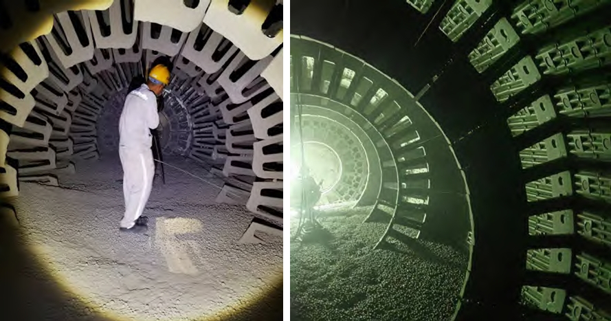
Figure 5: Schematic of actual processing of frozen sand molds: (a) green casting forming machine tool; (b) schematic of frozen sand mold processing
Figure 6: Schematic of load gripping direction
3. Theoretical Analysis of Frozen Sand Mold Stress
3.1 Three – Dimensional Mathematical Model of Frozen Sand Mold Force Balance
At – 20°C, frozen sand molds are brittle. Under the condition of stable clamping without damage, they can be described by the elastic mechanics theory of three – dimensional objects. During the clamping process, the surface of the frozen sand mold bears uniform stress, and its interior is subjected to pressure or tension from the fixture. To maintain the internal force balance of the frozen sand mold, the internal stress and external force must be in equilibrium. As a brittle object, the stress and deformation degree of the frozen sand mold are directly related to the external force. Only when the external force applied to the frozen sand mold does not exceed its compressive strength will elastic deformation occur. When the external force disappears, the frozen sand mold will return to its original shape, and the corresponding internal stress will cause elastic deformation inside the frozen sand mold. The force – bearing model of the frozen sand mold on each surface is shown in Figure 7. The force balance equations are as follows: \(\sum F_{x}=\frac{\partial \sigma_{x}}{\partial x}+\frac{\partial \tau_{y x}}{\partial y}+\frac{\partial \tau_{x x}}{\partial z}+x = 0\) \(\sum F_{y}=\frac{\partial \tau_{x y}}{\partial x}+\frac{\partial \sigma_{y}}{\partial y}+\frac{\partial \tau_{z y}}{\partial z}+y = 0\) \(\sum F_{z}=\frac{\partial \tau_{x z}}{\partial x}+\frac{\partial \tau_{y z}}{\partial y}+\frac{\partial \sigma_{z}}{\partial z}+z = 0\)
Figure 7: Schematic of force model for frozen sand molds
These equations can describe the force – balance state during the clamping of frozen sand molds.
3.2 Two – Dimensional Mathematical Model of the Strain Plane of Frozen Sand Molds
When clamping a frozen sand mold, the axial direction is not stressed. The two – dimensional force diagram of the thin – walled part of the frozen sand mold is shown in Figure 8. The length direction is taken as the z – axis, and the two end – faces cannot move along the z – axis direction. Suppose the frozen sand mold is cut into many thin slices along the z – axis direction. Although their force – bearing situations are the same, due to the different shapes of the cast parts, the thickness of each plane is different, resulting in different strains on each plane. The stress – strain and displacement components of these thin slices of the frozen sand mold can be regarded as functions of x and y in the xoy plane and are independent of the z – coordinate. Therefore, it can be approximately considered that the axial displacement \(w = 0\) at each point on any cross – section of the frozen sand mold. The three strain components \(\varepsilon_{x}\), \(\varepsilon_{y}\), and \(\gamma_{s}\) parallel to the xoy coordinate plane only deform within the cross – section. Thus, the three – dimensional strain problem of clamping a frozen sand mold can be transformed into a two – dimensional plane – strain problem, and then the situation with the maximum strain of the frozen sand mold can be analyzed under different conditions. The balance equations are: \(\frac{\partial \sigma_{x}}{\partial x}+\frac{\partial \tau_{y x}}{\partial y}+x = 0\) \(\frac{\partial \tau_{x y}}{\partial x}+\frac{\partial \sigma_{y}}{\partial y}+y = 0\) The geometric equations are: \(\varepsilon_{x}=\partial u / \partial x\) \(\varepsilon_{y}=\partial v / \partial y\) \(\gamma_{x y}=\partial u / \partial y+\partial v / \partial x\) The physical model equations are: \(\varepsilon_{x}=\frac{1-\mu^{2}}{E}\left(\sigma_{x}-\frac{\mu}{1-\mu} \sigma_{y}\right)\) \(\varepsilon_{y}=\frac{1-\mu^{2}}{E}\left(\sigma_{y}-\frac{\mu}{1-\mu} \sigma_{x}\right)\) \(\gamma_{x y}=\frac{2(1 + \mu)}{E} \tau_{x y}\)
Figure 8: 2D force diagram of thin – walled components in frozen sand mold
3.3 Compressive Constitutive Relationship of Frozen Sand Molds
In engineering, frozen sand molds and some materials (such as frozen soil, rock, and concrete) exhibit reversible deformation characteristics within the small – deformation range, meaning they can return to their original state after unloading. The microscopic mechanism of elastic deformation is that under the action of force, the distance between microscopic particles in the object changes, but its microscopic structure remains unchanged. When the force is unloaded, the interaction force between microscopic particles causes them to return to the initial state. Therefore, elastic deformation is only related to the magnitude of the load, and there is a one – to – one correspondence between stress and strain. In this study, the following model was used to define the constitutive equation of the elastic stage of frozen sand molds under compression at low temperatures: \(\left\{\begin{array}{l} \sigma<\sigma_{*}\\ \sigma = E\varepsilon_{e}\\ \sigma_{s}=\sigma_{0}-K V_{p}\\ \varepsilon=V / L=\varepsilon_{e}+V_{p} / L \end{array}\right.\) where \(\sigma_{*}\) and \(V_{P}\) are the strength and plastic deformation of the sand – grain micro – element in the current state; \(\sigma_{0}\) is the strength limit in the initial state or when \(V_{P}=0\); \(\varepsilon\) and \(\varepsilon_{e}\) are the apparent strain and elastic strain respectively, V is the compression deformation, and L is the length of the sand – grain micro – element.
Based on the established constitutive model, at a low temperature of – 20°C, with different water contents (4%, 6%, 8%) of frozen sand molds made of silica sand, zircon sand, and chromite sand, and different contact surfaces of clamping plates (rubber, polyurethane, steel plate), finite – element simulation analysis was carried out on the frozen sand molds with different compressive stresses, according to the parameter values of the compressive constitutive model of frozen sand molds shown in Table 1.
| Frozen Sand Mold | Temperature \(T/^{\circ}C\) | Compressive Strength \(\sigma_{bc}/MPa\) | Elastic Modulus \(E/MPa\) | Sand Grain Size / Mesh | Density \((g\cdot cm^{-3})\) | Poisson’s Ratio \(\mu\) |
|---|---|---|---|---|---|---|
| Silica Sand (Water Content 4%) | – 20 | 2.187 | 122.15 | 100 | 2.44 | 0.211 |
| Silica Sand (Water Content 6%) | – 20 | 2.448 | 123.23 | 100 | 2.34 | 0.232 |
| Silica Sand (Water Content 8%) | – 20 | 2.551 | 124.13 | 100 | 2.30 | 0.241 |
| Zircon Sand (Water Content 4%) | – 20 | 2.429 | 126.21 | 100 | 4.09 | 0.252 |
| Chromite Sand (Water Content 4%) | – 20 | – | – | 100 | – | – |
Table 1: Parameters of the constitutive model for frozen sand molds under compression
4. Numerical Simulation Study on Clamping Deformation of Frozen Sand Mold Thin – Walled Parts
4.1 Analysis of Clamping Deformation of Frozen Sand Molds with Different Wall Thicknesses at Different Water Contents
Simulation experiments were conducted on frozen sand molds with different water contents. The water contents (mass fractions) of the frozen sand molds were 4%, 6%, and 8% respectively, the material was 100 – mesh silica sand, and the contact surface material of the clamping plate was a steel plate. Using the above experimental parameters, numerical simulations were carried out on frozen sand molds with different wall thicknesses for clamping and analysis [17]. Figure 9 shows the situation of clamping a silica sand frozen sand mold with a water content (mass fraction) of 4%. During the clamping process, when the wall thickness is 40mm, the compressive stresses of frozen sand molds with water contents (mass fractions) of 4%, 6%, and 8% are 0.073699 MPa, 0.77602 MPa, and 0.79876 MPa respectively, which are less than the compressive strength. The frozen sand molds are stably clamped without damage. However, the frozen sand molds undergo a certain degree of elastic deformation. When the wall thickness is 40mm, the strain at the easily – deformed part of the frozen sand mold is smaller than that of other wall – thickness cases. Due to the structural differences of each part of the frozen sand mold when 受力 (under stress), the bearing forces are different, resulting in different deformation amounts. At the part with poor force – bearing capacity, the maximum elastic strain generated at the easily – deformed thin – wall part is 0.00060409.
| Water Content (Mass Fraction) | Wall Thickness (mm) | Compressive Stress (MPa) | Maximum Elastic Strain at Easily – Deformed Part |
|---|---|---|---|
| 4% | 40 | 0.073699 | 0.00060409 |
| 6% | 40 | 0.77602 | 0.00063091 |
| 8% | 40 | 0.79876 | 0.00064367 |
Figure 9: Silica sand frozen sand mold elastic strain with water content (mass fraction) of 4%: (a) wall thickness is 10mm; (b) wall thickness is 20mm; (c) wall thickness is 30mm; (d) wall thickness is 40mm; (e) wall thickness is 50mm
Figure 10(a) shows the situation of clamping a silica sand frozen sand mold with a water content (mass fraction) of 6%. When the wall thickness is 40mm, the maximum elastic strain at the easily – deformed part is 0.00063091. Figure 10(b) shows the situation of clamping a silica sand frozen sand mold with a water content (mass fraction) of 8%. When the wall thickness is 40mm, the minimum elastic strain at the easily – deformed part is 0.00064367.
Figure 10: Silica sand frozen sand mold elastic strain with different water contents (mass fraction): (a) 6%; (b) 8%
4.2 Analysis of Clamping Deformation of Frozen Sand Molds with Different Wall Thicknesses Made of Different Materials
Simulation experiments were carried out on frozen sand molds made of different materials. As known from Section 3.1, when the water content (mass fraction) of the frozen sand mold is 4%, the elastic deformation generated at the most easily – deformed part is the smallest. By the method of controlling variables, the water content (mass fraction) of the sand mold was selected as 4%, the sand mold materials were 100 – mesh zircon sand and 100 – mesh chromite sand respectively, and the contact surface material of the clamping plate was a steel plate. Numerical simulations were carried out on frozen sand molds with different wall thicknesses for analysis. During the clamping process, when the wall thickness is 40mm, the compressive stresses of frozen sand molds made of 4% zircon sand and 4% chromite sand are 0.10998 MPa and 0.11831 MPa respectively,which are less than the compressive strength, and no damage occurs. As shown in Figure 11(a), when the frozen sand mold made of 4% zircon sand with a wall thickness of 40mm is stably lifted, the strain at the easily – deformed part is less than that of other wall – thickness cases, and the maximum strain is 0.00087287. As shown in Figure 11(b), when the frozen sand mold made of 4% chromite sand with a wall thickness of 40mm is clamped, the maximum elastic strain at the easily – deformed part is 0.00091713.
| Sand Mold Material | Water Content (Mass Fraction) | Wall Thickness (mm) | Compressive Stress (MPa) | Maximum Elastic Strain at Easily – Deformed Part |
|---|---|---|---|---|
| Zircon Sand | 4% | 40 | 0.10998 | 0.00087287 |
| Chromite Sand | 4% | 40 | 0.11831 | 0.00091713 |
Figure 11: Frozen sand mold elastic strain with water content (mass fraction) of 4%: (a) zircon sand; (b) chromite sand
4.3 Analysis of Clamping Deformation of Frozen Sand Molds with Different Wall Thicknesses at Different Contact Surfaces
Simulation experiments were carried out on frozen sand molds clamped with different clamping – plate contact surfaces. As known from Sections 3.1 and 3.2, when the contact surface is a steel plate, the elastic deformation generated at the most easily – deformed part of the frozen sand mold made of 4% silica sand is the smallest. By the method of controlling variables, the water content (mass fraction) was selected as 4%, the sand mold material was 100 – mesh silica sand, and the contact – surface materials of the clamping plates were rubber plates and polyurethane plates respectively. Numerical simulations were carried out on frozen sand molds with different wall thicknesses for clamping. During the clamping process, the compressive stresses when the frozen sand molds are stably clamped by the rubber plate and the polyurethane plate are 0.0449832 MPa and 0.060581 MPa respectively, which are less than the compressive strength, and no damage occurs. As shown in Figure 12(a), when the frozen sand mold made of 4% silica sand with a wall thickness of 40mm is stably lifted by the rubber – plate surface, the maximum elastic strain at the easily – deformed part is 0.00036748. As shown in Figure 12(b), when the frozen sand mold made of 4% silica sand with a wall thickness of 40mm is stably lifted by the polyurethane – plate surface, the maximum elastic strain at the easily – deformed part is 0.00049657.
| Contact Surface Material | Water Content (Mass Fraction) | Wall Thickness (mm) | Compressive Stress (MPa) | Maximum Elastic Strain at Easily – Deformed Part |
|---|---|---|---|---|
| Rubber Plate | 4% | 40 | 0.0449832 | 0.00036748 |
| Polyurethane Plate | 4% | 40 | 0.060581 | 0.00049657 |
Figure 12: Elastic strain when rubber – plate surface (a) and polyurethane – plate surface (b) clamp silica – sand frozen sand mold with water content (mass fraction) of 4%
5. Conclusion
Through experiments and numerical simulations of frozen sand molds under different conditions, the following conclusions can be drawn:
(1) When the water content of the frozen sand mold is the same, the friction coefficient between the frozen sand mold made of silica sand and different contact surfaces is smaller than that of the frozen sand molds made of zircon sand and chromite sand. This indicates that silica – sand – based frozen sand molds have better sliding performance on contact surfaces, which may be beneficial for reducing the risk of surface damage during the clamping process.
(2) Under the same wall thickness, compared with clamping frozen sand molds with water contents (mass fractions) of 6% and 8%, clamping a frozen sand mold with a water content (mass fraction) of 4% results in the smallest deformation. This suggests that an appropriate water content can optimize the mechanical properties of frozen sand molds during clamping, reducing the degree of elastic deformation and ensuring the integrity of the mold.
(3) Under the same wall thickness, compared with clamping frozen sand molds made of zircon sand and chromite sand, clamping a frozen sand mold made of silica sand results in the smallest deformation. In addition, compared with using polyurethane plates and steel plates as contact surfaces for clamping frozen sand molds, using a rubber – plate surface leads to the smallest deformation. This shows that the choice of sand – mold material and contact – surface material has a significant impact on the clamping deformation of frozen sand molds. The rubber – plate surface provides better cushioning and adhesion properties, reducing the stress concentration on the frozen sand mold and minimizing deformation.
These findings provide valuable references for the selection of frozen sand molds and the design of fixtures in practical engineering applications. In future research, more in – depth studies can be carried out on the long – term performance and fatigue characteristics of frozen sand molds under different clamping conditions to further improve the reliability and efficiency of the frozen – sand – mold casting process.