1. Introduction
In recent years, the development of sand mold 3D printing technology has brought new impetus to the casting industry. This technology breaks through the limitations of traditional casting methods, enabling the production of complex – shaped, thin – walled, lightweight, and precise castings. It is widely used in aerospace, automotive, shipbuilding, and other fields. However, during the 3D printing process of sand molds, some problems need to be addressed. For example, the relationship between process parameters and sand mold performance is complex. Increasing the content of binders and curing agents to obtain high – strength sand molds will lead to an increase in gas evolution and affect the forming accuracy. At the same time, inappropriate printing layer thickness will also have an impact on sand mold strength and printing efficiency. Therefore, it is necessary to optimize the sand mold 3D printing forming process to improve the quality of castings and reduce production costs.
2. Sand Mold 3D Printing Technology
2.1 Working Principle
Sand mold 3D printing is based on the principle of powder discrete deposition and micro – droplet inkjet. Premixed sand is vibrated and dropped onto the printing platform by a sand – spreading device to form a sand bed. The binder is ejected from the print head onto the forming area of the sand bed surface. The binder penetrates and diffuses between sand grains to form resin bridges, which bond the sand grains together, thus realizing the printing of the target sand mold. This process is different from traditional molding methods. Traditional methods require mixing additives with raw sand, and then compacting the sand in a mold to form a sand mold, while 3D printing can directly print the sand mold according to the digital model without the need for complex molds and compaction operations.
2.2 Process Parameters
- Resin Inkjet Content: It refers to the mass fraction of resin in the molding sand of each forming area during the 3D printing process. Resin is the key component for bonding sand grains. An appropriate increase in resin inkjet content can enhance the bonding strength between sand grains, thereby improving the tensile strength of the sand mold. However, too high a resin content will lead to an increase in gas evolution during the casting process, which may cause casting defects such as porosity.
- Curing Agent Addition: The curing agent is added to promote the curing reaction of the resin. It accounts for a certain mass fraction of the premixed sand. The addition of the curing agent affects the curing rate and quality of the resin. If the amount is too small, the resin may not be fully cured, resulting in insufficient sand mold strength. If the amount is too large, it may accelerate the reaction rate too much, causing problems such as uneven curing and affecting the overall performance of the sand mold.
- Printing Layer Thickness: Also known as Z – resolution, it determines the number of layers of the sand mold during the printing process. A smaller layer thickness can improve the surface quality and accuracy of the sand mold, but it will increase the number of sand – spreading operations and reduce the printing efficiency. A larger layer thickness can improve the printing efficiency, but it may weaken the bonding force between sand layers and reduce the strength of the sand mold.
3. Optimization Experiment Design
3.1 Experimental Materials and Equipment
- Materials: The raw sand used in the experiment is silica sand, the binder is 3D – printed furan resin, and the curing agent is 3D – printed curing agent. The main performance indicators of these materials are shown in Table 1.
3.2 Box – Behnken Response Surface Method
The Box – Behnken (BBD) response surface method is a commonly used optimization method in experimental design. In this study, it is used to optimize the sand mold 3D printing forming process. Taking resin inkjet content, curing agent addition, and printing layer thickness as parameter variables, and the tensile strength and gas evolution of the sand mold as performance responses, a three – factor three – level BBD experiment design is carried out through optimization experiment design software. The factors and level coding of the experimental design are shown in Table 2.
| Level | Resin Inkjet Content(A)/% | Curing Agent Addition(B)/% | Printing Layer Thickness(C)/mm |
|---|---|---|---|
| 1 | 1.35 | 0.20 | 0.25 |
| 2 | 1.50 | 0.30 | 0.35 |
| 3 | 1.65 | 0.40 | 0.45 |
3.3 Casting Process Design
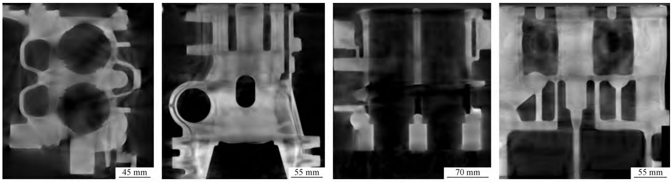
A certain type of thin – walled impeller casting is selected as the verification object for the optimization of the 3D printing sand mold forming process. The overall contour size of the impeller is 318 mm×318 mm×124 mm, the maximum wall thickness is 44.5 mm, the minimum wall thickness is 1.2 mm, and the wall thickness is uneven. Sixteen groups of blades surround the center to form the special – shaped inner cavity of the casting, and the overall structure is complex. The casting quality is 6.3 kg, and the material is ZL101A alloy. Considering the structure and material characteristics of the impeller, the casting method is determined to be sand mold low – pressure casting. The gating system is an open – type, and the cross – sectional area ratio of each unit of the gating system is \(\sum A_{in}:\sum A_{runner}:\sum A_{gate}=1.0:2.1:2.3\). The 3D printing casting process design model is shown in Figure 1.
4. Experimental Results and Analysis
4.1 Tensile Strength Response Surface Analysis
- Variance Analysis: The variance analysis results of the tensile strength are shown in Table 3. The model \(P<0.0001\), much less than 0.005, and the F value is 56.68, indicating that the model is very significant. The P value of the lack – of – fit term is 0.5055>0.1, and the F value is 0.9256, indicating that the lack – of – fit is not significant. The experimental results can be predicted by this model. In addition, the correlation coefficient \(R^{2}=0.9865\), indicating a high degree of fit between the measured and predicted values of the tensile strength. The corrected determination coefficient \(R_{Adj}^{2}=0.9691\), indicating that less than 4% of the tensile strength cannot be explained by this model. The coefficient of variation \(C_{v}=2.58\%\), indicating a low deviation between the measured and predicted values, and the experimental results are reliable.
4.2 Gas Evolution Response Surface Analysis
- Variance Analysis: The variance analysis results of gas evolution are shown in Table 4. The model \(P(<0.0001)<0.005\), and the F value is 564.2, indicating that the model is very significant. The P value of the lack – of – fit term is 0.3245>0.1, and the F value is 1.59. Compared with the pure error, the lack – of – fit term is not significant, and the model is suitable for predicting the experimental results. The correlation coefficient \(R^{2}=0.9986\) and the corrected determination coefficient \(R_{Adj}^{2}=0.9969\) verify the goodness of fit of the model, indicating a high degree of consistency between the measured and predicted values of gas evolution. The coefficient of variation \(C_{v}=0.849\%\), indicating a low deviation between the measured and predicted values, and the experimental results are reliable.
4.3 Parameter Optimization and Performance Prediction
In practical production, a high – strength sand mold with low gas evolution and reduced raw material consumption is desired. Using the Numerical function in the optimization experiment design software, the process parameters were optimized based on the response surface analysis. The results are presented in Table 5.