1. Introduction
Volute products play a crucial role in various industries, such as in pumps, turbines, and compressors. Their unique curved structure makes the casting process challenging. The traditional casting methods, including mold sand – core casting and 3D printing core – assembly, both face issues like mold extraction and sand – core handling. To address these problems, a well – designed three – dimensional casting process is essential. This article will delve into every aspect of the three – dimensional casting process of volute products, from model preparation to the final design of sand cores and molds.
1.1 Significance of Volute Products
Volute products are mainly used for gas collection, speed reduction, pressure increase, and gas discharge. For example, in a pump, the volute helps to efficiently direct the fluid flow, improving the pump’s performance. The design of the volute’s shape is carefully crafted to ensure uniform distribution of the fluid and minimize energy losses. Table 1 shows some common applications of volute products and their specific functions.
| Application | Function of Volute |
|---|---|
| Pumps | Guides fluid flow, increases pressure, and improves pumping efficiency |
| Turbines | Converts kinetic energy of fluid into mechanical energy effectively |
| Compressors | Assists in compressing gas and delivering it at a higher pressure |
1.2 Challenges in Casting Volute Products
The curved and complex structure of volute products poses several difficulties in the casting process. In mold sand – core casting, the mold extraction is a major concern. The non – planar maximum contour line of the volute wall makes it hard to determine the proper parting surface. If the parting surface is not designed correctly, it may lead to problems like mold – pulling sand during extraction, which can damage the mold and the casting. In 3D printing core – assembly, issues such as sand – core cleaning, placement, and fixation need to be addressed. Table 2 summarizes the challenges in different casting methods.
| Casting Method | Challenges |
|---|---|
| Mold Sand – Core Casting | Difficult mold extraction due to non – planar parting surface; potential for mold damage during extraction |
| 3D Printing Core – Assembly | Sand – core cleaning, proper placement, and secure fixation |
2. Simplifying the Model Structure
Before starting the casting process design, it is necessary to simplify the volute product model. This step is crucial as it helps to streamline the subsequent design procedures and avoid unnecessary complexity.
2.1 Deleting
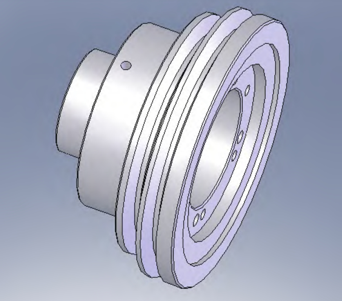
The first step in simplifying the model is to remove the ,such as holes and grooves. These structures are usually added in the post – casting machining process and do not need to be considered during the initial casting design. Additionally, all fillets except the main arc – shaped structures should be removed. However, it is advisable to keep a backup of the original model (referred to as Body 1) for future reference when adding fillets back. Figure 1 shows the original model and the model after removing the .
[Insert Figure 1: Comparison of the original volute model and the model after removing the
2.2 Importance of Model Perspective
When deleting the ,it is important to view the model in perspective. This allows for a clear view of the hidden structure lines and surfaces, preventing accidental deletion of important parts of the model. To increase the efficiency of simplification, the model can be rotated to concentrate the structure lines of the in one area with fewer other structure lines. Then, these structure lines can be selected using the box – selection method, and any unwanted selections can be deselected by reversing the selection. Table 3 lists the steps for simplifying the model structure.
| Step | Action |
|---|---|
| 1 | Backup the original model as Body 1 |
| 2 | Enter the model simplification mode |
| 3 | Rotate the model to gather lines |
| 4 | Use box – selection to choose lines |
| 5 | Reverse – select to deselect unwanted lines |
| 6 | Delete the selected |
3. Designing the Machining Allowance
The machining allowance design is a critical part of the casting process design for volute products. It ensures that the final product meets the required dimensional accuracy after machining.
3.1 Identifying and Marking Machining Surfaces
First, the machining surface markings on the 2D drawing provided by the customer need to be identified. Then, corresponding areas on the 3D volute model are marked with a distinct color (different from the main model color). After marking, the model structure is further simplified, focusing on the structures formed by the marked machining surfaces. Structures such as beveled surfaces, small – spaced grooves, and small steps that may cause difficulties in sand – core removal are removed. Figure 2 shows the model before and after simplifying the machining – surface – related structures.
[Insert Figure 2: Model before and after simplifying machining – surface – related structures]
3.2 Designing and Verifying the Machining Allowance
After simplifying the machining – surface – related structures, the model is backed up as Body 2. The machining allowance is then designed by thickening the marked machining surfaces according to the specified allowance size. As the allowance is designed, each processed surface can be marked with another color. After all allowances are designed, it is necessary to verify the design. Check if the machining – surface color is completely replaced, which indicates no omission in adding the allowance. Also, overlap the model with the machining allowance and Body 2, and view it in perspective. If the marked machining surface on Body 2 shows the main – model color at the same position, it means that an allowance has been added to a non – machining surface, and this needs to be corrected. Table 4 details the steps for designing and verifying the machining allowance.
| Step | Action |
|---|---|
| 1 | Backup the model as Body 2 |
| 2 | Mark machining surfaces on the 3D model according to 2D drawing |
| 3 | Simplify machining – surface – related structures |
| 4 | Design machining allowance by thickening marked surfaces |
| 5 | Mark designed allowance surfaces with a new color |
| 6 | Check color replacement for machining – surface allowance |
| 7 | Overlap with Body 2 and check for non – machining – surface allowance errors |
4. Extracting the Main Structure of the Volute Model
To accurately design the parting surface, it is necessary to first extract the main structure of the volute model. This step helps to obtain a clean and complete surface for further design.
4.1 Separating Additional Structures
Volute models often have structures like lifting lugs and bosses on their walls for lifting, assembly, and support. These structures can interfere with the extraction of the maximum contour line. To address this, they need to be separated from the volute wall. When separating these structures, it is important not to simplify any features that are not shown in the customer’s 2D drawing or add new features. They should be split into independent bodies from their joint surfaces. Figure 3 shows the process of separating the lifting lugs and bosses from the volute wall.
[Insert Figure 3: Process of separating lifting lugs and bosses from the volute wall]
4.2 Cleaning the Main Structure Surface
After separating the additional structures, these structures are hidden, and the main volute structure is independently displayed. However, the joint surfaces left on the volute wall after separation can cause problems when extracting the maximum contour line. These joint surfaces are not part of the same smooth surface as the volute wall. Therefore, these joint surfaces need to be deleted to make the volute wall a smooth and continuous surface. Table 5 shows the steps for extracting the main structure of the volute model.
| Step | Action |
|---|---|
| 1 | Locate and select lifting lugs, bosses, etc. on the volute wall |
| 2 | Separate these structures from the volute wall at their joint surfaces |
| 3 | Hide the separated structures |
| 4 | Display the main volute structure independently |
| 5 | Delete the joint surfaces on the volute wall |
5. Designing the Process Subsidy on the Volute Wall
In the casting process, various defects may occur. To prevent the occurrence of defects such as slag inclusions, a process subsidy needs to be designed on the volute wall.
5.1 Reasons for Adding Process Subsidy
Slag inclusions are a common casting defect. They usually occur on the top surface of the casting due to the floating of slag in the molten metal. In the case of volute products, the vertical surface of the model is arc – shaped, and during the mold – closing process, it is difficult to observe if there are any slag or sand particles falling into the cavity. Therefore, in addition to controlling the production process and optimizing the gating system, a certain amount of subsidy needs to be added to the top surface of the volute model. Figure 4 shows the potential position of slag inclusions in a volute casting.
[Insert Figure 4: Potential position of slag inclusions in a volute casting]
5.2 Method of Adding Process Subsidy
The surfaces that need to be subsidized on the volute model are the top surface of the outer wall and the bottom surface of the inner cavity. Since the volute wall is a spiral – ring structure, to maintain the side – dimension of the wall, the subsidy cannot be directly added to the entire surface. Instead, a transition subsidy is added to the top surface of the volute wall. This is done by duplicating the main volute model (after removing lifting lugs and bosses) at the same position, with one serving as the main body and the other as the subsidy body. The subsidy body is then moved by a distance ‘a’ (the subsidy amount) in the direction of the subsidy. Unnecessary parts of the subsidy body, such as flange parts, are removed, and then the two bodies are combined into one. Table 6 details the steps for adding the process subsidy.
| Step | Action |
|---|---|
| 1 | Duplicate the main volute model (without lifting lugs and bosses) |
| 2 | Designate one as the main body and the other as the subsidy body |
| 3 | Move the subsidy body by the subsidy amount ‘a’ |
| 4 | Remove unnecessary parts from the subsidy body |
| 5 | Combine the main body and the subsidy body into one |
6. Determining the Parting Surface
The parting surface is a key factor in the casting process as it affects the mold – making and casting operations. For volute products, the determination of the parting surface is more complex due to their curved structure.
6.1 Extracting the Maximum Contour Line and Creating the Bottom Template
The parting surface of a volute product is usually at the maximum contour of the volute wall. First, the maximum contour line of the volute wall is extracted. Then, using the mold – extraction direction as the vector, the maximum contour line is stretched into a sheet – like structure. The stretching distance should exceed the farthest point of the volute model in the stretching – vector direction. The stretched sheet is then thickened in both positive and negative directions to form a solid structure, which is one of the bottom templates of the upper and lower molds. Figure 5 shows the process of extracting the maximum contour line and creating the bottom template.
[Insert Figure 5: Process of extracting the maximum contour line and creating the bottom template]
6.2 Trimming and Adjusting the Bottom Template
After creating the bottom template, its edges need to be trimmed to match the shape of the volute main structure. This helps to reduce the sand – to – metal ratio. The bottom surface of the bottom template (opposite to the parting surface) is also trimmed to be horizontal when the volute model is placed horizontally, and its height should be higher than the highest point of the volute model. The center of the bottom template is filled to interfere with the volute model, but not to exceed the parting surface, outer – edge surface, and bottom surface. Finally, the previously separated lifting lugs and boss structures are combined with the volute main structure, and fillets are added according to the backup model (Body 1) and the customer’s drawing. The bottom template is then trimmed using the volute model with fillets as a cutting tool. Table 7 lists the steps for trimming and adjusting the bottom template.
| Step | Action |
|---|---|
| 1 | Trim the edges of the bottom template to match the volute shape |
| 2 | Trim the bottom surface of the bottom template to be horizontal |
| 3 | Fill the center of the bottom template |
| 4 | Combine lifting lugs and bosses with the volute main structure |
| 5 | Add fillets to the volute model |
| 6 | Trim the bottom template using the volute model with fillets |
7. Designing the Sand Core and Mold
The internal structure of volute products is a cavity, which requires the design of sand cores to form the correct shape during casting.
7.1 Designing the Sand Core for the Inner Cavity
The inner cavity of the volute product is a spiral – shaped cavity. It can be designed as an integral snail – shaped sand core. Core prints are designed at the openings connected to the outside, such as at the bottom – surface round hole and the pipe – opening position, for positioning. However, no core print is designed at the top – surface round – hole position to avoid sand – dropping during mold – closing, which could cause sand – inclusion defects in the casting. Figure 6 shows the design of the sand core for the inner cavity.
[Insert Figure 6: Design of the sand core for the inner cavity]
7.2 Ensuring the Accuracy of Sand – Core Placement
Since the volute product has a thin – wall structure, the accurate placement of the inner – cavity sand core is crucial. The center of gravity of the snail – shaped sand core is not at the center, so an internal fixture can be designed to increase the strength of the sand core, adjust its center of gravity, and guide the core – setting process. Additionally, to prevent the sand core from floating during casting, a core – marking hole is designed at the pipe – opening core – print position, and a corresponding fixture for embedding the core – marking is designed on the mold. This helps to fix the sand core in place. Table 8 shows the measures for ensuring the accuracy of sand – core placement.
| Measure | Function |
|---|---|
| Designing an internal fixture | Increases sand – core strength, adjusts center of gravity, and guides core – setting |
| Designing a core – marking hole and fixture | Prevents sand – core floating during casting |
8. Conclusion
The three – dimensional casting process of volute products involves multiple steps, from model simplification to sand – core and mold design. Each step is crucial and affects the final quality of the casting. By following the methods described in this article, such as proper model simplification, accurate machining – allowance design, and reasonable parting – surface determination, the efficiency of the casting process design can be significantly improved. At the same time, the occurrence of casting defects can be effectively reduced, and the quality of volute products can be guaranteed. Future research can focus on further optimizing these processes, such as exploring new materials for sand cores to improve their performance, or using advanced simulation software to better predict and prevent casting defects. Table 9 summarizes the key points of the three – dimensional casting process of volute products.
| Process Step | Key Points |
|---|---|
| Model Simplification | Remove and fillets; keep backup model; use perspective view for accurate deletion |
| Machining Allowance Design | Identify and mark machining surfaces; simplify related structures; verify allowance design |
| Main Structure Extraction | Separate additional structures; clean main – structure surface |
| Process Subsidy Design | Add subsidy to prevent slag inclusions; use transition – subsidy method |
| Parting – Surface Determination | Extract maximum contour line; create and trim bottom template; add fillets |
| Sand – Core and Mold Design | Design integral sand core for inner cavity; ensure sand – core accuracy |
In conclusion, a well – designed three – dimensional casting process is the key to producing high – quality volute products. By continuously improving and optimizing this process, the manufacturing industry can meet the increasing demands for volute products in various fields.