
In modern engine manufacturing, the precision machining of inclined oil holes in engine cylinder blocks remains a critical challenge due to strict geometric tolerances and complex material properties. This paper presents an integrated approach to designing a specialized fixture system that enables simultaneous drilling of five inclined oil holes in a four-cylinder engine block, significantly improving production efficiency while ensuring machining accuracy.
1. Machining Challenges and Technical Requirements
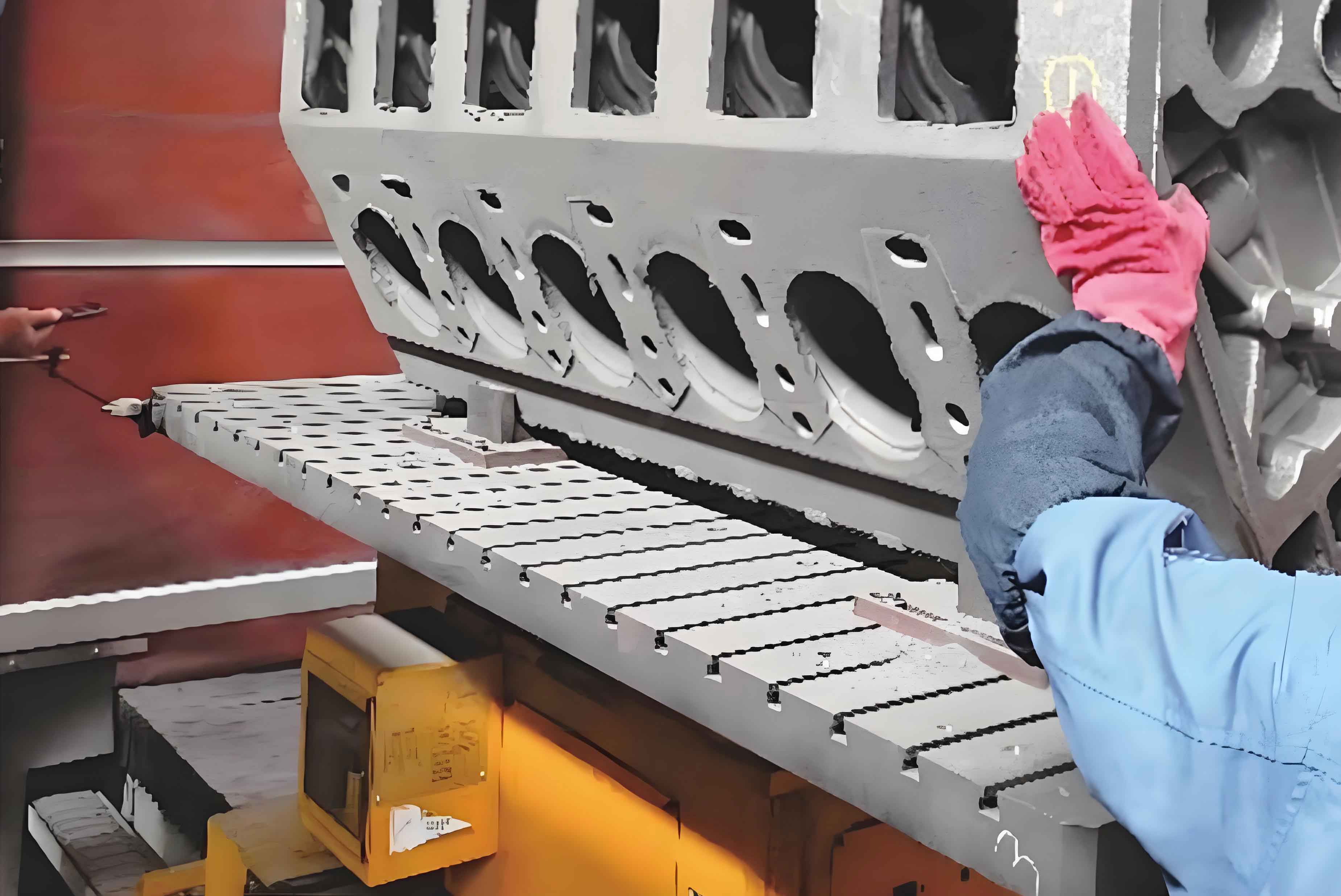
The inclined oil holes (32°15’±35′ from vertical axis) in engine cylinder blocks serve as critical lubrication channels connecting main bearings to connecting rod journals. Key machining challenges include:
- Deep hole drilling (L/D ratio > 20) with diameter Φ5mm
- Maintaining angular accuracy ±35′
- Preventing tool deflection and heat accumulation
- Ensuring chip evacuation efficiency
2. Fixture System Design Principles
The proposed fixture system employs rotational positioning mechanism combined with multi-axis synchronous drilling, featuring:
| Component | Specification |
|---|---|
| Positioning Accuracy | ±0.02mm |
| Clamping Force | 11-15 kN |
| Rotation Range | 0-35° |
| Tool Guidance | 5×Φ5±0.01mm Bushings |
The fundamental equation for calculating required clamping force considers both cutting forces and rotational inertia:
$$F_c = \frac{\mu(5F_a\sin\theta + G\cos\theta) + 5F_a\cos\theta}{\mu K}$$
Where:
$F_a$ = Axial cutting force (524.7N/hole)
$G$ = Workpiece weight (1500N)
$\mu$ = Friction coefficient (0.3)
$K$ = Safety factor (2)
3. Critical Subsystem Analysis
3.1 Positioning Mechanism
The “One Plane-Two Pin” system constrains all six degrees of freedom using:
- 400mm² primary locating surface
- Φ12H7 cylindrical pin (67A hole)
- Φ12H7/g6 diamond pin (67B hole)
3.2 Hydraulic Clamping System
A dual-stage hydraulic cylinder provides controlled clamping sequence:
$$P = \frac{4F}{\pi(D^2 – d^2)}$$
Where:
$P$ = Hydraulic pressure (5MPa)
$D$ = Piston diameter (60mm)
$d$ = Rod diameter (22mm)
3.3 Rotational Positioning Accuracy
The angular positioning error is minimized through:
$$ \Delta\theta = \arctan\left(\frac{\delta}{R}\right) $$
Where:
$\delta$ = Positioning block tolerance (0.01mm)
$R$ = Rotation radius (450mm)
4. Finite Element Verification
Static analysis of critical components using 20CrMnTi material properties:
| Parameter | Value |
|---|---|
| Elastic Modulus | 207 GPa |
| Yield Strength | 835 MPa |
| Poisson’s Ratio | 0.25 |
Stress distribution analysis shows maximum von Mises stress of 51.2 MPa at locating blocks, well below material yield strength. Deformation analysis confirms maximum displacement of 2.033μm, ensuring angular accuracy within required tolerance.
5. Automated Production Integration
The fixture system incorporates multiple sensors for process monitoring:
- 5× photoelectric sensors for tool alignment verification
- Non-contact switches for position feedback
- Pneumatic leak detection for locating confirmation
The complete machining cycle time is reduced to 85 seconds per engine cylinder block through simultaneous multi-hole processing and automated workpiece handling.
6. Conclusion
This integrated fixture design demonstrates significant improvements in engine cylinder block manufacturing:
- 85% reduction in machining time compared to sequential drilling
- Angular accuracy improvement from ±50′ to ±25′
- Tool life extension through optimized chip evacuation
The successful implementation confirms the effectiveness of combining rotational positioning with multi-axis synchronous drilling for complex geometry machining in engine cylinder block production.