
The manufacturing quality of diesel and gasoline engine cylinder blocks reflects a nation’s automotive industry development level. Lost Foam Casting (LFC), as a near-net-shape advanced manufacturing process, enables green production while meeting demands for increased power efficiency, reduced fuel consumption, and minimized emissions. This study demonstrates LFC’s superiority over traditional methods in engine cylinder block production through optimized process design and parameter control.
1. Characteristics of Engine Cylinder Block Castings
The HT250 low-alloy cast iron material composition for engine cylinder blocks follows strict chemical control:
| Element | Content (%) |
|---|---|
| C | 3.10–3.30 |
| Si | 1.60–1.80 |
| Mn | 0.60–0.75 |
| P | ≤0.050 |
| S | ≤0.060 |
| Cu | 0.6–1.0 |
| Cr | 0.3–0.5 |
Mechanical requirements include tensile strength ≥250 MPa and hardness 187–255 HBS after stress relief. The complex geometry containing cooling jackets, bearing housings, and multiple functional surfaces demands precision casting solutions.
2. Process Design and Implementation
2.1 Pattern Design Optimization
The horizontal parting design for foam patterns follows geometric complexity analysis:
$$
N_p = \frac{S_c}{S_t} \times \eta_m
$$
Where:
$N_p$ = Number of pattern segments
$S_c$ = Surface complexity index
$S_t$ = Standard segment complexity threshold
$\eta_m$ = Moldability factor (0.8–1.2)
Critical design parameters for engine cylinder block patterns:
| Parameter | Value |
|---|---|
| Draft angle | 1°–1.5° |
| Shrinkage allowance | 2.1%–2.4% |
| Wall thickness tolerance | ±0.3 mm |
| Surface roughness | Ra ≤12.5 μm |
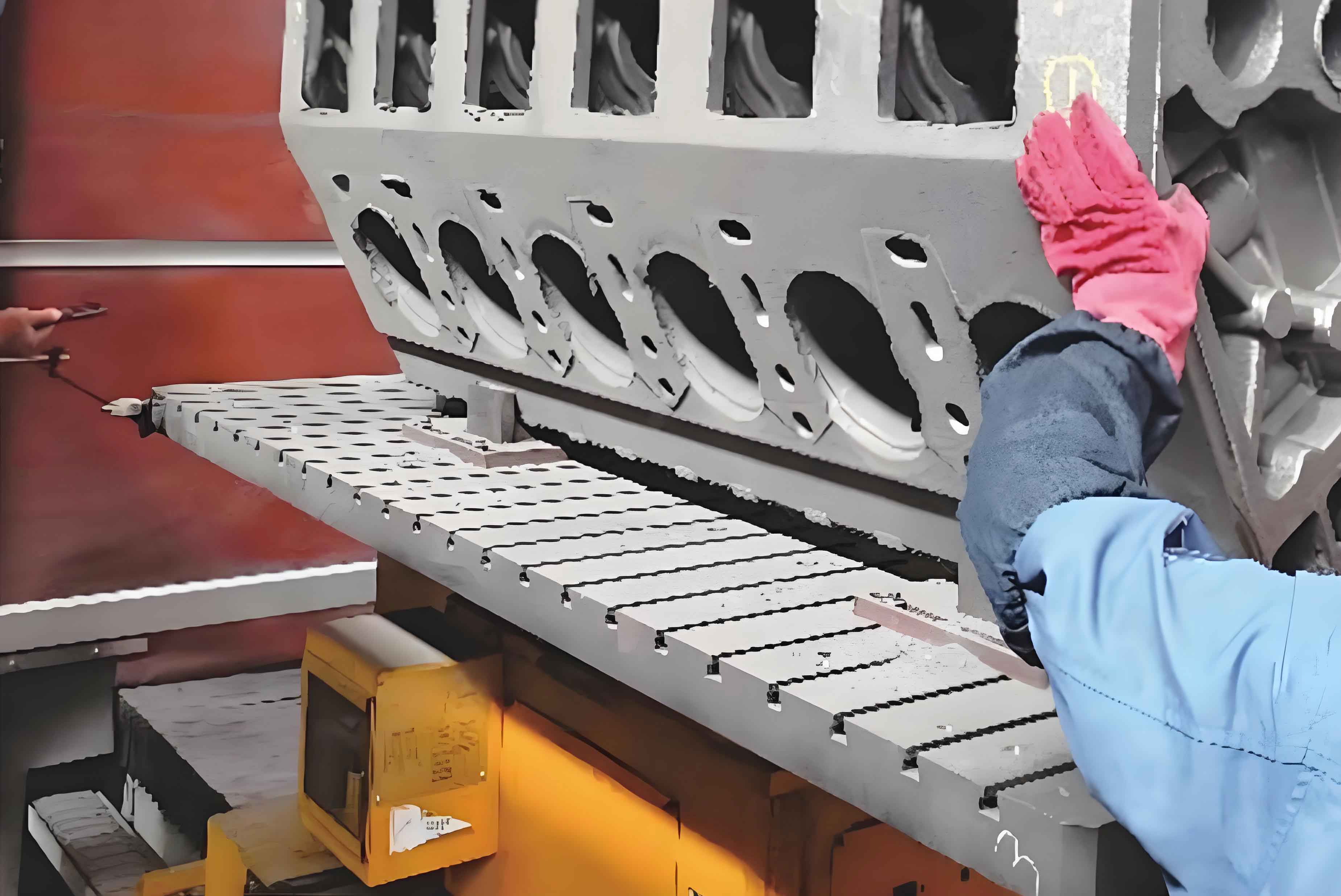
2.2 Foam Pattern Production
The expanded polystyrene (EPS) bead pre-expansion process follows:
$$
\rho_p = \rho_0 \times \left(\frac{D_0}{D_f}\right)^3
$$
Where:
$\rho_p$ = Pre-expansion density (20–21 g/L)
$\rho_0$ = Initial bead density
$D_0$ = Original bead diameter
$D_f$ = Final expanded diameter
Maturation time-temperature relationship:
$$
t_m = \frac{25}{\ln(T_a – 20)} \times e^{0.05\mathrm{RH}}
$$
Where:
$t_m$ = Maturation time (hours)
$T_a$ = Ambient temperature (°C)
$RH$ = Relative humidity (%)
3. Coating and Gating System
The coating thickness ($\delta_c$) for engine cylinder blocks follows:
$$
\delta_c = \frac{K_v \times \sqrt[3]{V_m}}{1 + \ln(\rho_p)}
$$
Where:
$K_v$ = Coating permeability coefficient (0.8–1.2)
$V_m$ = Mold volume (dm³)
Gating system design parameters:
| Component | Area Ratio | Dimension (mm) |
|---|---|---|
| Sprue | 1.3–2.0 | Ø40–50 |
| Runner | 1.0–1.5 | 30×40 |
| Ingate | 1.0 | 6×50 |
4. Process Validation
Production results demonstrate LFC advantages for engine cylinder blocks:
| Parameter | Traditional | LFC |
|---|---|---|
| Yield rate | 82% | 95% |
| Machining allowance | 3–5 mm | 1–2 mm |
| Energy consumption | 580 kWh/t | 320 kWh/t |
| Sand usage | 1.8 t/t | 1.1 t/t |
The optimized process achieves 91% metal yield with dimensional accuracy CT8–CT9. Post-casting inspection shows 99% machining qualification rate, proving LFC’s capability in producing high-quality engine cylinder blocks.
5. Conclusion
Lost Foam Casting demonstrates significant advantages in engine cylinder block production through:
- Reduced process steps (40% fewer than traditional methods)
- Improved material utilization (15–20% sand reduction)
- Enhanced dimensional accuracy (50% tolerance improvement)
- Superior surface quality (Ra 12.5 vs. 25 μm)
The successful implementation confirms LFC’s viability for mass production of complex engine components while meeting environmental and economic requirements.