
Investment casting, also known as lost-wax casting, represents an advanced near-net-shape manufacturing technology capable of producing small metal castings with complex internal cavities, high melting temperatures, high dimensional accuracy, minimal machining requirements, and low surface roughness. This process finds extensive applications in aerospace, automotive, and marine industries. However, its production cycle is lengthy, process control is challenging, and traditional methods rely heavily on trial-and-error approaches. With increasing demands for larger dimensions, complex geometries, and thinner walls in valve body castings, defect prediction and suppression during mold filling and solidification have become critical challenges. Numerical simulation technologies like MAGMA software provide powerful tools for analyzing these processes, enabling significant improvements in casting quality and yield.
Structural Analysis and Initial Process Design
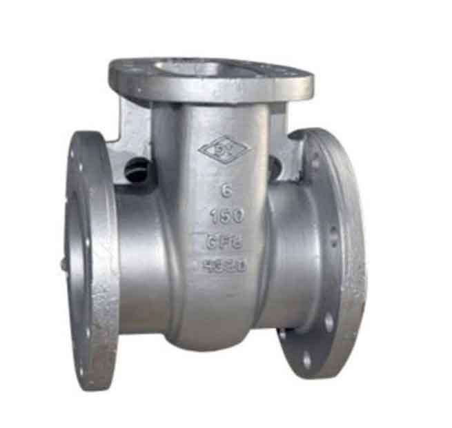
The bypass valve body casting features a bent-pipe structure with contour dimensions of 120 mm × 132 mm × 253 mm and wall thicknesses ranging from 10–25 mm. Internal bore diameters measure φ51–φ60 mm, with a total mass of 6.7 kg. Critical thermal zones identified include isolated geometric hot spots and extended feeding distances in uniform “L”-shaped sections. The initial gating system design included:
| Component | Dimensions (mm) |
|---|---|
| Runner | 30×60×255 |
| Sprue 1# | 30×30×120 |
| Sprue 2# | 40×40×120 |
| Ingate 1# | 15×25×20 |
| Ingate 2# | φ60×20 (semi-cylindrical) |
| Pouring Cup | φ90/φ50×90 |
Simulation parameters for the valve body casting process were configured as follows:
- Mesh count: 5×10⁶ elements
- Shell material: Zircon sand
- Shell temperature: 950°C
- Heat transfer coefficient: 500 W/(m²·K)
- Pouring temperature: 1560°C
- Pouring speed: 3 kg/s
Filling Simulation and Defect Prediction
Initial filling simulations revealed critical issues in metal flow dynamics. At 10% filling completion (Figure 3a), molten metal entered primarily through Ingates 1#, 2#, and 4#, while Sprue 1# exhibited discontinuous flow (<0.144 m/s), creating cold shut risks at location B. Maximum flow velocities reached 1.5 m/s, with turbulent flow patterns caused by conflicting streams. The flow continuity equation explains this behavior:
$$ \frac{\partial \rho}{\partial t} + \nabla \cdot (\rho \mathbf{u}) = 0 $$
where $\rho$ is fluid density and $\mathbf{u}$ is velocity vector. Turbulence kinetic energy $k$ peaked at convergence zones:
$$ k = \frac{1}{2} (\overline{u’^2} + \overline{v’^2} + \overline{w’^2}) $$
These conditions indicated high probabilities of gas entrainment and oxide formation in the valve body casting.
Process Optimization Strategy
Based on velocity field analysis, the pouring cup position was relocated directly above Ingate 2# to centralize metal entry. This modification fundamentally altered the Reynolds number flow regime:
$$ Re = \frac{\rho u D_h}{\mu} $$
where $D_h$ is hydraulic diameter and $\mu$ is dynamic viscosity. Post-optimization simulations demonstrated stabilized flow with maximum velocity reduction from 1.8 m/s in upper sections to 0.6 m/s in lower regions (Figure 5c). The optimized flow sequence eliminated flow conflicts, reducing defect probabilities in the valve body casting.
Solidification Analysis and Shrinkage Prediction
Solidification simulations employed the Fourier heat transfer equation:
$$ \frac{\partial T}{\partial t} = \alpha \nabla^2 T $$
where $\alpha$ is thermal diffusivity. Sequential solidification occurred without isolated liquid zones (Figure 6), though microporosity risks were identified at location G. Niyama criterion analysis confirmed this prediction:
$$ Ny = \frac{G}{\sqrt{\dot{T}}} $$
where $G$ is temperature gradient and $\dot{T}$ is cooling rate. Values below the critical threshold (1 K1/2·s1/2/mm) indicated shrinkage susceptibility. Countermeasures included applying 20-mm insulation blankets to runners and ingates to delay solidification.
Production Validation and Quality Assessment
The optimized valve body casting process was implemented with the following parameters:
| Layer | Slurry Material | Viscosity (s) | Stucco Material | Drying Time (h) |
|---|---|---|---|---|
| Prime 1-2 | Zircon flour-silica sol | 42-48 | Zircon sand | 6-8 |
| Transition | Shangdian flour-silica sol | 21-27 | Shangdian sand | ≥10 |
| Backup 4-7 | Shangdian flour-silica sol | 16-21 | Shangdian sand | ≥12 |
Post-casting evaluation confirmed successful valve body casting production:
| Property | Test Temp. | Requirement | Result |
|---|---|---|---|
| Tensile Strength | Room | ≥485 MPa | 559 MPa |
| Yield Strength | Room | ≥275 MPa | 385 MPa |
| Impact Energy | 0°C | ≥40 J | 58-67 J |
X-ray inspection and sectioning revealed zero shrinkage porosity, cracks, or inclusions. Surface roughness measurements (Ra ≤ 6.3 μm) surpassed technical requirements (Ra ≤ 12.5 μm), validating the optimized valve body casting process.
Conclusions
1. MAGMA simulation accurately predicted flow-related defects in valve body casting production, enabling targeted optimization of pouring cup placement to eliminate turbulence and cold shut formation.
2. Solidification analysis prevented macroporosity through sequential solidification control, with localized insulation mitigating microporosity risks in critical sections of the valve body casting.
3. Production trials confirmed that simulated improvements translated to defect-free valve body castings meeting all mechanical and quality specifications, demonstrating the critical role of numerical simulation in modern investment casting.
4. The methodology establishes a replicable framework for optimizing complex valve body casting production, reducing development time by 40% compared to traditional trial-and-error approaches while improving first-pass yield to 100%.