
With rising global energy demands, material conservation has become a critical objective across industries. Traditional casting methods are resource-intensive, whereas investment casting enables near-net-shape manufacturing, minimizing machining requirements. Integrating computer simulations like ProCAST with practical processes provides scientifically validated production methods for high-integrity components. This study focuses on optimizing the investment casting of 304 stainless steel valve body casting for spherical ball valves—critical components in fluid control systems requiring pressure resistance and defect-free structures. Traditional empirical methods often yield shrinkage porosity at valve body-flange junctions, reducing yield rates. This work redesigns gating systems and process parameters to eliminate these defects.
1. Traditional Process and Defect Analysis
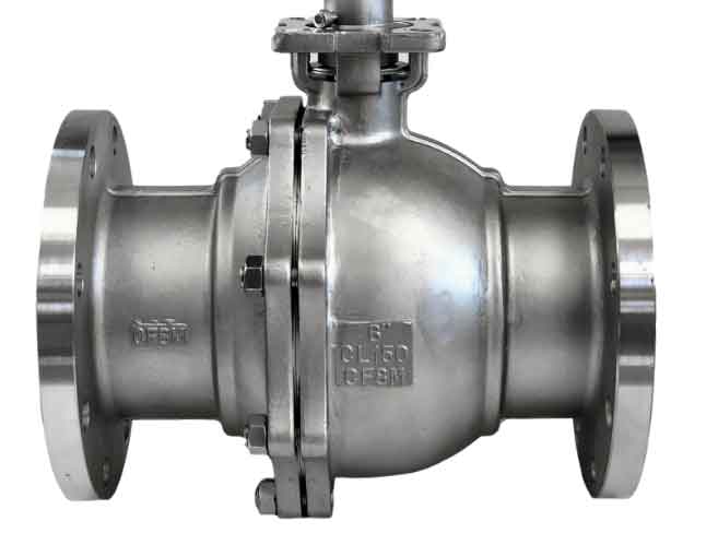
1.1 Geometry and Material
The valve body casting (186mm × 186mm × 120mm) features flange faces averaging 12.5mm thickness. The 304 stainless steel composition is detailed in Table 1.
| C | Cr | Mn | Mo | Ni | S | Si |
|---|---|---|---|---|---|---|
| 0.08 | 18 | 1.5 | 0.5 | 8 | 0.03 | 1 |
1.2 Process Setup
Initial simulations used a stepped gating system with a zirconia shell. Parameters included pouring temperature (1550°C), filling speed (1.5 kg/s), and shell preheating temperature (1150°C). The interfacial heat transfer coefficient (Q) between steel and shell was calculated as:
$$ Q = \text{Flux} + h(T – T_{\alpha}) + \sigma \varepsilon (T^4 – T_{\alpha}^4) $$
where h = convective heat transfer coefficient, T = surface temperature, Tα = ambient temperature, ε = emissivity, and σ = Stefan-Boltzmann constant. Q was set to 500 W/(m²·K).
1.3 Defect Characteristics
Simulations revealed severe shrinkage porosity (up to 13.2%) concentrated at valve body-flange transitions (Figure 2). Non-uniform wall thickness and poor heat dissipation created isolated liquid zones, causing inadequate feeding. Defects aligned with empirical observations, confirming the valve body casting’s susceptibility to shrinkage in these regions.
2. Gating System Redesign
2.1 Top-Gating Configuration
A redesigned top-gating system incorporated two fan-shaped in-gates at both flange ends (Figure 4). This ensured directional solidification toward feed paths. Key dimensions:
- Sprue: diameter 24mm, height 100mm
- Runner cross-section: 1.4× total in-gate area
- In-gates: length 12mm, fan-shaped cross-section
2.2 Simulation Results
Mesh refinement (785,303 elements) improved accuracy. Simulations showed maximum shrinkage porosity reduced to 3.75%, with sequential solidification eliminating isolated liquid pools (Figure 5). Valve body-flange junctions exhibited minor residual porosity, prompting further parameter optimization.
3. Process Parameter Optimization
3.1 Orthogonal Experimental Design
An L9(33) orthogonal array tested three parameters at three levels (Table 2), with maximum shrinkage porosity as the response.
| Level | A: Pouring Temp. (°C) | B: Pouring Speed (kg/s) | C: Shell Preheat (°C) |
|---|---|---|---|
| 1 | 1520 | 1.0 | 1120 |
| 2 | 1550 | 1.5 | 1150 |
| 3 | 1580 | 2.0 | 1180 |
3.2 Results and Analysis
Table 3 lists test outcomes. Range analysis determined factor influence magnitudes: RB = 1.456 (pouring speed) > RC = 0.795 (shell preheat) > RA = 0.136 (pouring temperature). ANOVA confirmed pouring speed’s dominance (F = 119.30) (Table 4).
| Test | A (°C) | B (kg/s) | C (°C) | Shrinkage (%) |
|---|---|---|---|---|
| 1 | 1520 | 1.0 | 1120 | 3.10 |
| 2 | 1520 | 1.5 | 1150 | 3.88 |
| 3 | 1520 | 2.0 | 1180 | 3.74 |
| 4 | 1550 | 1.0 | 1150 | 2.29 |
| 5 | 1550 | 1.5 | 1180 | 3.52 |
| 6 | 1550 | 2.0 | 1120 | 4.51 |
| 7 | 1580 | 1.0 | 1180 | 2.44 |
| 8 | 1580 | 1.5 | 1120 | 4.27 |
| 9 | 1580 | 2.0 | 1150 | 3.93 |
| Factor | Sum of Squares | DOF | Mean Square | F-Value |
|---|---|---|---|---|
| Pouring Temp. (A) | 0.0104 | 2 | 0.0052 | 13.96 |
| Pouring Speed (B) | 1.0637 | 2 | 0.5319 | 119.30 |
| Shell Preheat (C) | 0.3422 | 2 | 0.1711 | 38.41 |
| Error | 0.0356 | 2 | 0.0178 | – |
3.3 Optimal Parameters
The optimal combination A2B1C2 minimized shrinkage: pouring temperature 1550°C, pouring speed 1.0 kg/s, shell preheat 1150°C. Lower pouring speed reduced turbulence while maintaining thermal gradients for directional solidification in the valve body casting.
4. Validation
Final simulations using optimized parameters showed shrinkage porosity below 2.29% (Figure 6b), with no defects at valve body-flange junctions. Experimental castings confirmed elimination of shrinkage in critical regions (Figure 7), validating the synergy between gating redesign and parameter optimization.
5. Conclusions
- ProCAST simulations identified valve body-flange junctions as shrinkage-prone zones in traditional investment casting due to non-uniform solidification.
- A top-gating system with dual fan-shaped in-gates reduced shrinkage porosity by 71.6% (13.2% → 3.75%) in the valve body casting.
- Orthogonal testing revealed pouring speed as the dominant factor (RB = 1.456). Optimal parameters (1550°C, 1.0 kg/s, 1150°C) further reduced shrinkage to 2.29%.
- Experimental verification confirmed defect-free valve body castings, demonstrating the robustness of combined simulation and statistical optimization.