
Thick-section, geometrically complex high manganese steel (HMS) castings, like the ZGMn13 grade studied here, are critical components in demanding applications such as mining machinery (e.g., excavator front guide wheels). Their inherent properties – significant work hardening under impact for excellent wear resistance and slow crack propagation – make them indispensable. However, their large linear shrinkage (2.4% – 3.0%) and low thermal conductivity (approximately 1/4 to 1/6 that of carbon steel) present significant challenges during the casting process, leading to substantial thermal stresses and a high susceptibility to cracking, particularly in sections exceeding 120 mm thickness. This study investigates the root causes of micro-cracks observed in such castings.
1. Experimental Materials and Methods
The material under investigation was a finished ZGMn13 casting produced for mining machinery. The melt was prepared using pig iron, ferromanganese, and alloy steel in an electric furnace, followed by vacuum degassing (VD) to minimize oxygen content and control alloy oxidation. Chemical composition analysis of samples taken from cast-on blocks confirmed adherence to the GB/T 5680-1998 standard, as detailed in Table 1.
| Element | C | Si | Mn | P | S | Mo | Fe |
|---|---|---|---|---|---|---|---|
| ZGMn13 | 0.98 | 0.59 | 13.42 | 0.036 | 0.005 | 0.92 | Bal. |
| GB/T 5680-1998 | 0.90-1.30 | 0.30-0.80 | 11.00-14.00 | ≤0.040 | ≤0.070 | – | Bal. |
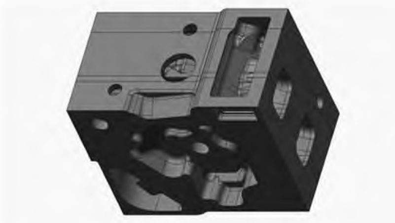
Samples containing micro-cracks were extracted from regions identified by penetrant testing (PT) on the casting surface (e.g., near holes or curved sections as indicated in Figure 1). Samples of dimensions 20 mm × 25 mm × 20 mm containing cracks and 30 mm × 30 mm × 20 mm samples from fully cracked areas were prepared. After mechanical grinding and polishing, samples were etched with a 4% Nital solution for approximately 6 seconds. Microstructural analysis and crack characterization were performed using optical microscopy and Nova-NanoSEM450 field emission scanning electron microscopy (SEM). Energy dispersive spectroscopy (EDS) was employed to analyze the chemical composition of inclusions and phases adjacent to cracks and within the matrix.
2. Results and Discussion
The high linear shrinkage of HMS inherently generates significant internal stress if contraction is hindered during the casting process. Compounding this, the low thermal conductivity causes large temperature gradients within thick, complex sections during both cooling and subsequent heat treatment (typically water quenching after solutionizing at ~1050°C), resulting in substantial thermal stresses. Furthermore, the solidification microstructure of HMS often features coarse grains, columnar crystals, and brittle carbides/non-metallic inclusions segregated at grain boundaries. These factors collectively embrittle the casting. The presence of inclusions, carbides, and phosphorus eutectics at grain boundaries critically weakens cohesion, providing potential sites for crack initiation under thermal stress. Observed micro-cracks exhibited extensive distribution, appearing as linear or interconnected networks along grain boundaries under low magnification (Figure 3). Numerous carbides and inclusions were consistently found within and surrounding these crack paths.
2.1 Influence of Inclusions on Cracking
The high alloy content of HMS makes it prone to oxidation during melting and pouring. While larger oxide inclusions formed during melting may float out, smaller oxides generated during pouring tend to remain entrapped. During solidification, these oxide films accumulate at grain boundaries, disrupting the continuity of the metal matrix and severely reducing its strength, facilitating crack initiation during mechanical loading or stress application. SEM analysis (Figure 4) confirmed the co-location of cracks and inclusions. EDS identified these primarily as spherical alumina (Al₂O₃), complex oxides containing Al, Mg, Cr, irregular titanium nitride (TiN), and minor manganese sulfide (MnS) inclusions. These brittle oxide and nitride inclusions, located at grain boundaries, exhibit poor bonding with the matrix. Differential solidification contraction rates within the complex casting geometry, coupled with the mismatch in physical properties between inclusions and the steel matrix, create significant stress concentration zones around the inclusions, particularly irregular ones. This localized stress exceeds the weak interfacial strength, leading to micro-crack nucleation, as evidenced by micro-fracturing observed around irregular inclusions (Figure 4).
2.2 Influence of Compositional Segregation on Cracking
2.2.1 Carbon and Manganese Segregation
Carbon atoms act as interstitial solutes in the Fe-Mn matrix, causing lattice distortion and creating stress fields. The combined effect of these stress fields and C-Mn atomic clusters impedes dislocation motion, enhancing strength. Carbon also stabilizes the austenite phase field, enabling the formation of a single-phase austenitic structure that provides good ductility and toughness. However, excessive C and Mn levels promote the precipitation of secondary cementite and, crucially, coarse grain boundary carbides detrimental to mechanical properties. Calculated phase diagrams illustrating C and Mn segregation effects are shown in Figure 5.
Microstructural examination (Figure 6) revealed substantial precipitation of chain-like, acicular, and blocky carbides, predominantly forming continuous networks along grain boundaries in the studied casting. Such continuous networks severely impair properties. All carbides in HMS tend towards the M₃C cementite structure but exhibit significant compositional variations, as determined by EDS (Table 2). Blocky carbides (~10 μm, Fig 6b) were identified as phosphide eutectic products with a fine, irregular lamellar structure. Their composition includes Fe, Mn, C, and Mo, with an Fe/Mn ratio of approximately 2.2, indicating high Mn content. These were found both at grain boundaries and within grains. Acicular carbides (<5 μm wide, ~30 μm long, Fig 6c,d) showed a distinct needle-like morphology with an Fe/Mn ratio of 3.4-3.6, indicating lower Mn content. Finer chain-like carbides (Fig 6e,f) exhibited an Fe/Mn ratio of 4.7-4.8, signifying even lower Mn content and higher alloying of the austenite matrix. The morphology, quantity, and composition of carbides are primarily dictated by local cooling rates during the casting process. Slower cooling promotes phosphide eutectic formation with high Mn content (Point A in Fig 6b confirmed as P-rich by EDS). Faster cooling hinders P diffusion, leading to fragmented eutectic and acicular carbide growth with reduced blocky carbide formation and lower Mn content in carbides. Regardless of morphology, these brittle phases weaken grain boundaries, creating sites for crack nucleation. Consequently, tensile stresses arising from solidification contraction and phase transformation readily initiate micro-cracks at these brittle carbide concentrations.
Fine carbides (<2 μm) nucleate first on austenite grain boundaries due to lower energy requirements and better lattice matching. Upon reaching a certain size, growth is hindered, and thicker carbides (>2 μm) form at the interface between fine carbides and the grain boundary. These thick carbides grow rapidly along the boundary, consuming finer ones. Their large size and poor lattice matching with austenite result in weak interfacial bonding, making them preferential sites for crack initiation and propagation under stress. The network distribution of these coarse carbides facilitates the development of interconnected crack networks (Fig 6a).
| Point | C | P | Mo | Mn | Fe | Fe/Mn |
|---|---|---|---|---|---|---|
| A | 1.29 | 1.21 | 4.84 | 28.59 | 62.77 | 2.2 |
| B | 3.52 | – | 74.00 | 9.77 | 8.57 | 0.9 |
| C | 2.94 | – | 1.87 | 21.69 | 73.08 | 3.4 |
| D | 2.15 | – | 2.19 | 20.65 | 75.56 | 3.6 |
| E | 2.23 | – | 1.95 | 16.71 | 78.52 | 4.8 |
| F | 1.28 | – | 1.29 | 16.38 | 80.10 | 4.7 |
2.2.2 Phosphorus Segregation
Phosphorus is a particularly detrimental impurity in HMS due to its low solubility in austenite. It readily segregates to grain boundaries and interdendritic regions, forming low-melting-point phosphide eutectics. The calculated phase diagram illustrating P segregation is shown in Figure 7. Phosphorus eutectics solidify in the final stages of the casting process, concentrating at grain boundaries and interdendritic spaces. This segregation drastically reduces intergranular cohesion, embrittling the grain boundaries and diminishing the hot plasticity of the steel. Furthermore, the standard HMS heat treatment temperature (~1050°C) exceeds the melting points of binary Fe-Fe₃P (1005°C) and ternary Fe-Fe₃C-Fe₃P (950°C) eutectics. During heat treatment, these eutectics melt, forming liquid films that severely weaken the boundary’s cohesion with the matrix. Under tensile stress (from quenching or residual stress), these liquid films act as potent sites for crack initiation and propagation, as observed in Figure 6d and Figure 8a.
Non-uniform cooling, inherent in thick, complex castings, exacerbates the problem. Increasing carbon content in austenite further reduces phosphorus solubility, promoting even greater segregation to grain boundaries and subsequent phosphide eutectic formation during final solidification. These phosphorus-rich zones become preferential sites for crack nucleation under stress. Cracks initiated by phosphide eutectics often appear as networks (Fig 6a), with voids and eutectic phases visible within the crack. EDS analysis (Fig 8) confirmed severe phosphorus segregation at the crack, with an atomic percentage of 12.20%. Crucially, even with moderate bulk P levels, significant segregation to boundaries can occur. Moreover, the low-melting-point eutectic wets austenite dendrites effectively, favoring continuous film formation along boundaries rather than discrete particles. This continuous distribution poses a far greater threat to mechanical integrity than isolated particles.
The detrimental effect of phosphorus segregation can be related to its solubility in austenite, which decreases with increasing carbon content. A simplified relationship can be expressed as:
$$S_p = k \sqrt{C}$$
where \(S_p\) is the solubility limit of P, \(k\) is a segregation coefficient dependent on composition and cooling rate, and \(C\) is the carbon concentration. Lower \(S_p\) promotes greater P enrichment at boundaries.
3. Conclusions and Improvement Strategies for the Casting Process
1. The presence of significant carbides and inclusions segregated at grain boundaries forms brittle phases that embrittle the boundaries, leading to cracking. To mitigate the negative impact of carbide networks, strict control of chemical composition and precise optimization of the solution heat treatment parameters (temperature, holding time, cooling rate) within the casting process is essential. This ensures complete dissolution of detrimental phases and prevents re-precipitation of grain boundary carbides.
2. Carbon and Manganese exert a synergistic effect. Elevated levels and/or segregation promote the formation of coarse grain boundary carbides, drastically weakening the matrix. Under tensile stresses inherent in solidification and cooling, micro-cracks readily initiate and propagate at these sites, causing a precipitous drop in ductility and toughness. For enhanced resistance in thick sections, controlling carbon content within 1.15% – 1.20% and manganese around 13% is recommended during the alloy design stage of the casting process.
3. Phosphorus (and Sulfur) impurities are significant contributors to cracking in austenitic manganese steel castings. Phosphorus segregation to austenite grain boundaries leads to the formation of low-melting-point phosphide eutectics during the final stages of the casting process. These eutectics drastically reduce grain boundary strength, making them highly susceptible to intergranular cracking under thermal stress. Therefore, stringent control of phosphorus input via raw materials is paramount. Additionally, strategies to minimize its detrimental effects include increasing solidification cooling rates where feasible (e.g., optimized chills), employing homogenization treatments before solutionizing, and exploring microalloying additions that can tie up phosphorus or modify eutectic morphology.
4. Minimizing oxide and nitride inclusion formation through effective melt deoxidation practices (like VD used here), careful handling during pouring, and mold design to minimize turbulence is critical. Controlling inclusion morphology (reducing irregular shapes) can also lessen stress concentration during the casting process.
5. Optimizing gating and risering design, along with strategic use of chills, is vital to promote more directional solidification and reduce thermal gradients, thereby minimizing the tensile stresses that drive crack initiation and propagation in thick, complex HMS castings.