
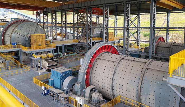
The ball mill serves as the cornerstone of cement grinding operations. Our manufacturing facility operates five M4213 ball mills supplied by Shenyang Cement Machinery Co., Ltd. between 2007-2008. After 16 years of service under conditions of frequent power interruptions and cyclic loading, two ball mills developed critical cracks (100-1,000mm long, 30-55mm deep) at the fillet weld between the sliding shoe and web plate on the mill head side. This article details our online repair methodology and performance validation.
Problem Analysis
Operational stresses combined with material fatigue led to weld defects. For Ball Mill #2, magnetic particle and ultrasonic testing revealed:
| Component | Defect Type | Dimensions |
|---|---|---|
| Head-side fillet weld | Cracks + manufacturing defects | 1.7m crack + 870mm defects (24-40mm deep) |
| Tail-side fillet weld | Cracks + manufacturing defects | 600mm crack + 1,600mm defects (20-53mm deep) |
| Cylinder circumferential welds | Manufacturing defects | 7 welds with incomplete fusion |
The stress concentration factor at weld joints follows:
$$K_t = 1 + 2\sqrt{\frac{a}{\rho}}$$
Where \(a\) = crack depth and \(\rho\) = root radius. Cyclic loading conditions accelerated failure:
$$N_f = \frac{C}{\Delta \sigma^m}$$
Where \(N_f\) = cycles to failure, \(\Delta \sigma\) = stress range, and \(C\), \(m\) = material constants.
Online Repair Methodology
Pre-repair Inspection
Compliance standards for weld inspection:
| Method | Standard | Acceptance Criteria |
|---|---|---|
| Ultrasonic | GB/T 11345 II.B | No indications > 3mm |
| Penetrant | GB 9443-1988 | Class II |
| Material UT | GB/T 2970 | No planar defects |
Welding Procedure
Deformation control during welding required real-time monitoring:
$$\delta = \frac{\alpha Q}{\rho c} \cdot \frac{V}{A}$$
Where \(\delta\) = distortion (mm), \(\alpha\) = thermal expansion coefficient, \(Q\) = heat input (J/mm), \(\rho\) = density, \(c\) = specific heat, \(V\) = weld volume, \(A\) = cross-section area. Key parameters:
| Parameter | Control Value | Measurement |
|---|---|---|
| Interpass temperature | <150°C | Infrared thermometer |
| Bead thickness | <4mm | Weld gauge |
| Radial tolerance | <0.4mm | Dial indicators |
Weld repair sequence:
- Preheat to 120°C minimum
- Controlled air-carbon arc gouging (max depth/pass: 5mm)
- Multi-layer SMAW welding using E7018 electrodes
- Post-weld heat treatment at 250°C for 2 hours
Post-weld Processing
Surface machining requirements after repair:
$$R_a < 0.8\mu m \quad \text{and} \quad \text{Flatness} < 0.15mm$$
Material removal during machining followed:
$$Q = v \cdot f \cdot a_p$$
Where \(Q\) = removal rate (mm³/min), \(v\) = cutting speed (m/min), \(f\) = feed rate (mm/rev), \(a_p\) = depth of cut (mm). Final dimensional tolerances:
| Parameter | Specification | Achieved |
|---|---|---|
| Radial runout | <0.4mm (90% area) | 0.32mm |
| Surface roughness | Ra < 0.8μm | Ra 0.65μm |
| Weld reinforcement | 0-0.5mm | 0.3mm |
Performance Validation
Post-repair monitoring of Ball Mill #2 showed stable operation:
$$\Delta T = T_{\text{bearing}} – T_{\text{oil}} < 15^\circ \text{C}$$
Power consumption remained consistent with pre-failure data:
$$I_{\text{avg}} = 1,850 \pm 25 \text{A}$$
Subsequent inspection of Ball Mill #3 revealed similar defect patterns, confirming systemic manufacturing issues:
| Defect Type | Frequency | Max Depth |
|---|---|---|
| Incomplete fusion | 32 locations | 18mm |
| Slag inclusions | 27 locations | 14mm |
| Porosity clusters | 19 locations | 8mm |
Long-term Integrity Management
To prevent recurrence, we implemented:
1. Inspection protocol: Ultrasonic testing every 6 months focusing on stress concentration zones:
$$Z_{\text{critical}} = \frac{t \cdot \sin\theta}{1 – \cos\theta}$$
Where \(t\) = material thickness, \(\theta\) = weld angle.
2. Operational modifications:
- Reduced start-stop frequency by 40%
- Implemented ramped loading sequence
- Installed vibration monitoring sensors
3. Life extension formula:
$$L_{10} = \frac{16,000}{n^{0.3} \cdot P^{1.5}}$$
Where \(L_{10}\) = expected life (hours), \(n\) = start/stop cycles per month, \(P\) = power loading factor.
Conclusion
The online repair of the ball mill welding cracks demonstrates that comprehensive in-situ remediation is feasible for critical cement machinery. Our methodology preserved the structural integrity of the 16-year-old ball mill while avoiding costly disassembly. The repaired ball mill has operated for 8 months with no deviation in power consumption (1,850±25A), bearing temperatures (ΔT<15°C), or vibration signatures. This approach provides cement plants with a validated framework for extending the service life of aging ball mill infrastructure.