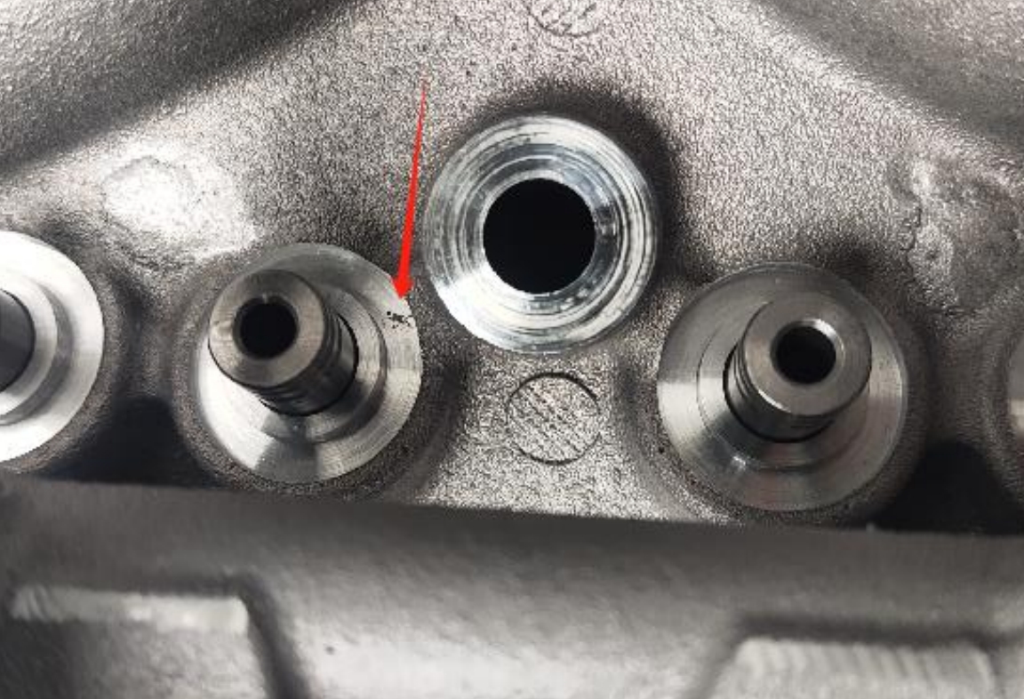
As foundry engineers specializing in heavy-truck axle components, we encountered persistent shrinkage cavity casting defects in the main reducing shell cover (dimensions: 554 mm × 350 mm × 138 mm, weight: 20 kg). This ductile iron (QT400-15) component features critical thick sections (37 mm) adjacent to thin walls (7 mm), creating inherent solidification challenges. Through systematic analysis and process refinement, we eliminated shrinkage cavity casting defects and achieved stable production.
Thermal Analysis and Solidification Challenges
Structural hotspots were identified at two critical locations:
| Hotspot Location | Modulus (cm) | Solidification Time Ratio* |
|---|---|---|
| Base Flange (Location 1) | 1.2 | 1.0x |
| Upper Ø125mm Bore (Location 2) | 2.8 | 5.4x |
*Relative to thin-wall sections. Solidification time follows Chvorinov’s Rule: $$ t = C \left( \frac{V}{A} \right)^2 $$ where \( t \) = solidification time, \( C \) = mold constant, \( V \) = volume, \( A \) = surface area.
Gating and Pouring Strategy Optimization
After testing pan-up vs. pan-down orientations, pan-down configuration was selected to minimize surface defects despite increased shrinkage cavity casting risks at Location 2. The gating system featured:
- Semi-open design: \( \Sigma S_{sprue} : \Sigma S_{runner} : \Sigma S_{ingate} = 1 : 1.15 : 1.3 \)
- Two ingates with 60×60×15mm 10PPI ceramic foam filter
- Controlled pour temperature: 1380–1400°C
Thermal simulations confirmed that ingates at Location 1 created a combined structural-process hotspot with a 40% longer solidification time versus structural hotspot alone.
Riser System Evolution for Shrinkage Cavity Casting Mitigation
Location 1 (Base Flange):
- Initial trials without risers showed shrinkage porosity (Fig. 4 reference)
- Solved with Ø55×85mm hot riser: Modulus ratio \( \frac{M_{riser}}{M_{hotspot}} = 1.8 \)
Location 2 (Upper Bore):
| Approach | Riser Dimensions | Defect Rate |
|---|---|---|
| No riser | – | 100% shrinkage cavity casting |
| Conventional riser | Ø80×110mm | 20% |
| Riser + exothermic sleeve | Ø80×110mm + heating block | 0% |
The exothermic riser extended solidification time by 2.3× through two mechanisms:
- Delayed heat transfer: \( q = -k \nabla T \) (reduced thermal gradient \( \nabla T \))
- Exothermic reaction energy: \( E_{exo} = \rho V C_p \Delta T \)
Riser neck offset design utilized sharp-sand effect to prolong feeding: $$ t_{neck} \propto \frac{1}{\sqrt{\theta}} $$ where \( \theta \) = sand angle.
Metallurgical Control for Reduced Shrinkage Tendency
Charge composition and melt practices were optimized:
| Parameter | Target | Effect on Shrinkage |
|---|---|---|
| Charge Ratio | 35% returns + 65% steel scrap | ↓ Trace elements |
| Carbon Equivalent (CE) | 4.55±0.05% | ↓ Shrinkage cavity casting risk |
| SiC Addition | 0.6-0.8% | ↑ Graphite nucleation |
| Residual Mg | 0.03-0.05% | ↓ Microporosity |
Final chemistry control limits:
| Element | Target (%) |
|---|---|
| C | 3.65–3.80 |
| Si | 2.55–2.80 |
| Mn | <0.30 |
| P | <0.06 |
| S | <0.02 |
| RE | <0.03 |
| Mg | 0.03–0.05 |
Integrated Solutions for Shrinkage Cavity Casting Prevention
- Orientation: Pan-down pouring minimized surface defects while requiring thermal management at Location 2
- Riser Design: Exothermic risers with offset necks provided directional solidification at critical hotspots
- Gating: Filtered bottom-gating ensured non-turbulent filling
- Metallurgy: Controlled CE and inoculation enhanced graphitization expansion to counter shrinkage cavity casting formation
The synergistic effect of these measures reduced solidification stress by: $$ \sigma_{therm} = \alpha E \Delta T $$ where \( \alpha \) = thermal expansion coefficient, \( E \) = Young’s modulus, \( \Delta T \) = temperature gradient.
Conclusion
Successful elimination of shrinkage cavity casting defects in main reducing shell covers required addressing both structural and process-induced hotspots. The implementation of exothermic risers with optimized neck design proved critical for isolated heavy sections. Combined with controlled metallurgy (CE=4.55±0.05%, Mg<0.05%) and pan-down pouring, scrap rates dropped from 100% to near zero. This systematic approach demonstrates that robust process design can overcome inherent shrinkage cavity casting challenges in complex ductile iron components.

