
Coal remains the cornerstone of energy security in China, given the nation’s resource profile characterized by abundant coal reserves but limited oil and natural gas. Coal storage silos, serving as critical infrastructure for energy enterprises, play a pivotal role in the storage and supply chain. Their fully enclosed design offers significant advantages over traditional open stockpiles, including minimized coal quality degradation, reduced dust pollution, and efficient material handling. A key component ensuring the longevity of these massive structures is the wear-resistant lining plate installed on vulnerable internal surfaces like the conical hopper, sloped walls, and near the discharge outlet, where intense coal impact and abrasion occur. Common materials for these critical protective elements include steel plates, cast basalt, ceramics, and particularly, rolled crystallite panels.
Rolled crystallite panels are widely employed as wear-resistant lining plates due to their exceptional hardness, smoothness, and abrasion resistance. However, their installation involves meticulous bonding to the concrete substrate using specialized microcrystalline grout. This complex process, coupled with the significant difference in thermal expansion coefficients between the concrete, grout, and crystallite panels, creates inherent vulnerabilities. Traditional methods for inspecting the condition of these lining plates face immense challenges. Silo interiors are confined spaces, characterized by poor lighting, potential toxic gas accumulation, and difficult accessibility due to the large diameter (often 40m) and height (over 40m). Manual inspection is hazardous, inefficient, and often fails to provide a comprehensive assessment of the lining plate integrity.
This article details the application of 3D laser scanning technology to overcome these limitations and conduct a thorough evaluation of wear-resistant lining plate defects within coal storage silos at Huanghua Port. The technology offers a paradigm shift in structural inspection, enabling safe, rapid, and highly accurate data capture of the silo’s internal geometry and lining plate condition.
Advantages of 3D Laser Scanning Technology
3D laser scanning operates by emitting laser beams that strike the target surface. The scanner measures the time-of-flight or phase shift of the reflected beams to calculate precise distances. By systematically rotating the laser emitter, the scanner captures millions of surface points per second, generating a dense “point cloud” representing the object’s 3D shape. For silo lining plate inspection, this technology provides distinct advantages:
- Enhanced Safety: Eliminates the need for personnel entry into potentially hazardous, confined, and poorly lit silo environments contaminated by coal dust and gases.
- High Precision: Capable of achieving sub-millimeter accuracy, allowing for the detection of minute deformations, cracks, or missing sections within the lining plate surface.
- High Efficiency: Completes comprehensive scans of large silo volumes within a fraction of the time required for manual methods, minimizing operational downtime.
- Comprehensive Coverage: Captures data from all accessible surfaces, including hard-to-reach areas like the hopper apex and upper silo walls, ensuring no defects are overlooked.
- Rich Data Visualization: Generates detailed 3D models and intensity/grayscale images, facilitating intuitive visualization, analysis, and quantification of lining plate conditions.
The core principle involves capturing the spatial coordinates (X, Y, Z) of surface points. The distance \(d\) from the scanner to a point is calculated using the time-of-flight principle:
$$d = \frac{c \cdot \Delta t}{2}$$
where \(c\) is the speed of light and \(\Delta t\) is the time difference between laser pulse emission and reception. The horizontal angle \(\theta\) and vertical angle \(\phi\) from the scanner’s internal encoders determine the point’s direction, yielding its 3D coordinates:
$$\begin{cases}
x = d \cdot \sin\theta \cdot \cos\phi \\
y = d \cdot \cos\theta \cdot \cos\phi \\
z = d \cdot \sin\phi
\end{cases}$$
For the Huanghua Port application, a Z+F IMAGER 5010C scanner was utilized. Its key technical specifications are summarized below:
| System | Parameter | Value |
|---|---|---|
| Laser System | Laser Class | 1 |
| Beam Divergence | < 0.3 mrad | |
| Beam Diameter (at 0.1m) | 3.5 mm | |
| Maximum Range | 187.3 m | |
| Minimum Range | 0.3 m | |
| Resolution | 0.1 mm | |
| Measurement Rate | 1,016,000 pts/s | |
| Deflection Unit | Vertical Field of View / Resolution | 320° / 0.0004° |
| Horizontal Field of View / Resolution | 360° / 0.0002° | |
| HDR Camera | Focus Range | 1m ~ ∞ |
| Number of Panoramic Images | 42 |
Common Failure Modes of Wear-Resistant Lining Plates
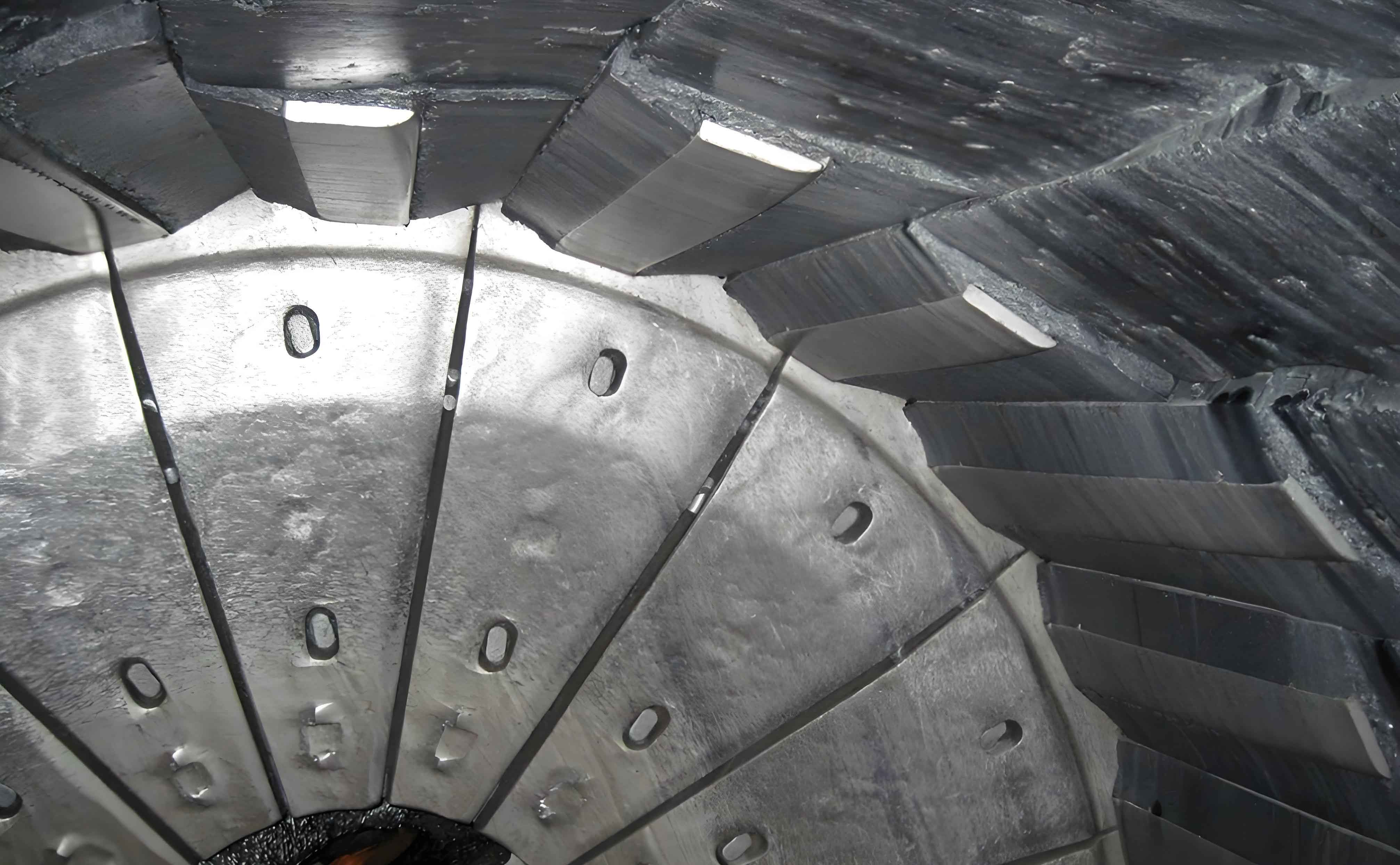
The wear-resistant lining plate is crucial for protecting the underlying concrete structure of the silo. In the Huanghua Port silos, rolled crystallite panels (14mm thick on slopes, 12mm on vertical walls) are bonded using microcrystalline grout (10mm thick, bond strength ≥ 3.0 MPa) onto concrete surfaces inclined at angles of 66°, 60°, and 50° relative to the horizontal plane. Despite their excellent wear properties, these lining plates are susceptible to specific failure modes:
- Localized Fracture: Individual panels can shatter upon direct impact from large coal lumps.
- Delamination and Detachment: The most common and critical failure. Differential thermal expansion/contraction cycles between the concrete substrate, grout layer, and crystallite panels can weaken the bond over time. Impact damage or inadequate initial bonding can initiate detachment. Crucially, the failure of one panel often creates stress concentrations, leading to progressive detachment of adjacent lining plates, potentially resulting in large-scale spalling.
Failure to promptly detect and repair detached lining plates has severe consequences:
- Concrete Degradation: Exposed concrete is subjected to direct abrasion from coal flow and corrosive elements within the stored coal. This leads to surface wear, loss of cover concrete, exposure of reinforcement, subsequent corrosion, cracking, and spalling, significantly compromising structural integrity.
- Material Hang-up and Blockage: Missing lining plates create rough surfaces where moist, fine coal particles readily adhere. This buildup forms uneven protrusions. Furthermore, lump coal can become trapped at the junction between the hopper slope and vertical wall, especially if fines fill the voids. Under the pressure of overlying coal, these blockages consolidate, impeding material flow, causing silo blockages, and in severe cases, creating conditions conducive to spontaneous combustion.
Therefore, regular, reliable inspection of the wear-resistant lining plate condition is paramount for proactive maintenance and ensuring silo safety and functionality.
Implementation: Scanning and Analysis Workflow
Inspecting the lining plates within the challenging environment of operational coal silos necessitates a robust methodology. The process involves field data acquisition and sophisticated computational processing:
1. Field Scanning Procedure:
- Reconnaissance: Assess the target silo, identifying optimal scan locations and access points. Given the confined space, scanning was performed by suspending the scanner inverted from the silo roof vent.
- Scanner Setup: Securely mount a tripod over the vent opening. Attach the scanner to the tripod via a rigid connecting rod, ensuring minimal vibration during rotation.
- Operation: Lower the inverted scanner into the silo. Control the scanner wirelessly (via WiFi) using a mobile device. Configure scan resolution and quality settings based on silo size and required detail.
- Data Acquisition & Export: Execute the scan. Verify data quality immediately after acquisition (e.g., coverage, absence of major voids). Export the raw point cloud data for processing.
2. Data Processing and Analysis Workflow:
- Preprocessing: Import raw scan data into Z+F LaserControl software. Perform essential preprocessing steps:
- Noise Filtering: Remove stray points caused by dust or scanner noise.
- Registration: Align multiple scan stations (if used) into a unified coordinate system using common tie points or surface matching algorithms. The transformation for aligning two point clouds, P and Q, involves finding rotation R and translation T minimizing:
$$\sum_{i=1}^{n} ||(R \cdot p_i + T) – q_i||^2$$
where \(p_i\) and \(q_i\) are corresponding points. - Color Mapping (Optional): Apply HDR panoramic images to the point cloud for visual context (though limited in dark silos).
- 3D Model Reconstruction: Generate a watertight 3D surface model (mesh) from the cleaned and aligned point cloud, accurately representing the current internal geometry, including the lining plate surfaces and any defects.
- Reference Model Creation: Utilize design drawings and scan data from intact lining plate areas to reconstruct an idealized 3D model representing the silo’s original, undamaged surface profile (pre-wear, pre-detachment).
- Defect Detection and Quantification:
- Lining Plate Detachment Identification: Analyze the 3D model and grayscale intensity images derived from the point cloud reflectivity. Lining plates appear as regular patterns with high reflectivity and form a relatively smooth surface. Detachment exposes concrete, appearing as irregular, discontinuous areas with medium-high reflectivity and forming concave depressions in the 3D model. Coal buildup appears as irregular convex shapes with very low reflectivity (near black in grayscale). Water seepage areas show no data points. Identify and delineate areas of missing lining plates.
- Detachment Area Calculation: Calculate the surface area of each identified lining plate detachment zone within the 3D model environment.
- Concrete Wear Depth Measurement: Using Geomagic Qualify software, compare the “as-built” scanned surface (current condition) against the “as-designed” reference model (original surface). The software calculates the deviation at every point, visualized as a color-coded deviation map. The wear depth \(D_w\) at any point is calculated as:
$$D_w = M_s – (T_p + T_g + E_s)$$
where:- \(M_s\) = Measured depth from the reference plane to the scanned surface point.
- \(T_p\) = Original lining plate thickness (14mm or 12mm).
- \(T_g\) = Original grout layer thickness (10mm).
- \(E_s\) = Construction tolerance/surface error derived from intact areas.
This quantifies the depth of concrete erosion beneath the missing lining plate.
- Statistical Analysis: Summarize detachment areas by location, calculate total detachment area and percentage, and analyze wear depth distribution.
Results: Defect Identification and Quantification
The application of 3D laser scanning successfully generated a comprehensive 3D model of the silo interior. Analysis of the model and associated grayscale images enabled clear identification and quantification of wear-resistant lining plate defects. The silo interior was divided into logical zones for detailed assessment: Vertical Walls, Support/Decompression Surfaces, Hopper Region (subdivided into N1, N2, N3, S1, S2, S3), and the Central Partition Beam surface.
1. Lining Plate Detachment: The analysis revealed distinct signatures in the data:
- Intact lining plates exhibited high-intensity returns and formed a geometrically regular, relatively smooth surface contour.
- Areas of lining plate detachment showed medium-high intensity (concrete exposure) and appeared as concave deviations from the expected surface plane in the 3D model.
- Coal accumulation zones displayed very low intensity and appeared as irregular convex protrusions.
Based on these signatures, 24 distinct detachment areas were identified and mapped. The total surface area covered by lining plates was 3054.0 m². The cumulative area of detachment was 286.8 m², corresponding to a detachment rate of 9.4%. The distribution varied significantly across zones:
| Zone | Zone Area (m²) | Detachment Area (m²) | Detachment Rate (%) | Detachment IDs |
|---|---|---|---|---|
| Vertical Walls | 690.8 | 34.7 | 5.0 | S1~S6 |
| Support/Decompression Surfaces | 827.2 | 35.0 | 4.2 | S7~S10, S23, S24 |
| Hopper N1 | 202.0 | 0.0 | 0.0 | – |
| Hopper N2 | 202.0 | 75.4 | 37.3 | S16, S17, S18 |
| Hopper N3 | 202.0 | 29.4 | 14.6 | S14, S15 |
| Hopper S1 | 202.0 | 3.1 | 1.5 | S22 |
| Hopper S2 | 202.0 | 15.8 | 7.8 | S21 |
| Hopper S3 | 202.0 | 19.3 | 9.6 | S19, S20 |
| Central Partition Beam | 324.0 | 74.1 | 22.9 | S11, S12, S13 |
| Total | 3054.0 | 286.8 | 9.4 | S1~S24 |
The detachment was concentrated primarily on the Central Partition Beam surface (22.9% detachment) and the Hopper N2 zone (37.3% detachment). This pattern aligns with operational mechanics: the Central Partition Beam lies directly beneath the central filling point, experiencing the highest impact energy from falling coal. The Hopper N2 zone likely suffered significant impact damage initiating localized lining plate failure, which subsequently propagated due to stress concentrations, leading to large-scale spalling. Zones experiencing lower impact and abrasion (Vertical Walls, Support Surfaces) showed significantly lower detachment rates.
2. Concrete Wear Assessment: For areas where the lining plate was detached, the depth of concrete wear beneath the original lining plate level was calculated using the deviation analysis method described earlier. The maximum measured wear depth was 34.7 mm, located within detachment area S17 (Hopper N2). Analysis of wear depth distribution across all detachment areas showed:
- ~80.3% of the detached area had wear depths between 0-10 mm.
- ~15.0% had wear depths between 10-20 mm.
- ~4.7% exhibited wear depths exceeding 20 mm.
Given a typical concrete cover depth of 50 mm for reinforcement, the results indicated that while significant wear had occurred in localized spots, no rebar exposure was detected in this scan. However, the areas exceeding 20mm wear warrant close monitoring in subsequent inspections. A representative deviation chromatogram clearly visualizes the wear depth variation within a detachment zone.
3. Validation: Post-scanning validation was performed using lowered explosion-proof lights and high-resolution cameras to photograph representative detachment areas identified in the 3D model. Comparison between the 3D model visualization and the physical photographs confirmed the accuracy of the defect location, size, and morphology identified by the laser scanning process. This validation step reinforced the reliability of 3D laser scanning for safely and accurately assessing lining plate conditions.
Conclusion
The successful implementation of 3D laser scanning technology for inspecting wear-resistant lining plates in Huanghua Port’s coal storage silos demonstrates its transformative potential for industrial asset management. This technology effectively addressed the critical limitations of traditional inspection methods – safety hazards, inefficiency, and incomplete coverage – within the challenging silo environment. By generating highly accurate 3D models and intensity data, the technology enabled precise identification, localization, and quantification of lining plate detachment areas and underlying concrete wear depths. The detailed defect mapping, particularly highlighting high-impact zones like the Central Partition Beam and Hopper N2, provides invaluable data for prioritizing repairs and optimizing maintenance strategies.
The quantification of concrete wear depth beneath detached lining plates offers crucial insights into the structural health of the silo itself, allowing engineers to assess the urgency of repairs based on remaining concrete cover. The high efficiency of data capture minimizes silo downtime, translating to significant operational cost savings. The comprehensive digital record created serves as an essential baseline for tracking degradation rates and planning future inspections. In conclusion, 3D laser scanning proves to be a safe, efficient, accurate, and indispensable tool for the inspection and maintenance of wear-resistant lining plates in coal storage silos, ensuring their structural integrity, operational reliability, and longevity. Its adoption is strongly recommended for proactive asset management in similar industrial settings.