
In the chemical industry, pump bodies made from CF8 stainless steel are critical components that operate under acidic conditions, demanding high internal quality, excellent surface finish, and precise dimensional accuracy. Due to their complex geometry and challenging formability, these castings are typically produced using the lost wax investment casting process. This method involves creating a wax pattern, coating it with a ceramic shell, melting out the wax, and pouring molten metal into the cavity. However, defects like shrinkage porosity and cavities often arise, particularly in sections with varying wall thicknesses, leading to potential failures under high-pressure conditions. In this study, we address these issues by leveraging numerical simulation to optimize the lost wax investment casting process for a CF8 stainless steel pump body, ensuring defect-free components that meet stringent customer requirements.
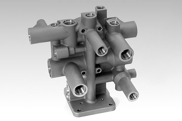
The CF8 stainless steel pump body, as analyzed, features an intricate design with non-uniform wall thicknesses, including thick sections at the inlet and outlet flanges and thinner areas in the flow channels and pump feet. Such disparities create thermal hotspots during solidification, making the casting prone to shrinkage defects. Traditional lost wax investment casting processes struggle with implementing chillers due to the ceramic shell’s nature, necessitating alternative strategies to control solidification sequences. We employed ProCAST software for numerical simulation to visualize and rectify these issues, focusing on optimizing the gating and feeding systems to promote directional solidification and eliminate isolated liquid zones.
The chemical composition of CF8 material, as specified in our analysis, is crucial for understanding its solidification behavior. The table below summarizes the key elements:
| Element | Content (wt.%) |
|---|---|
| C | 0.06 |
| Mn | 1.1 |
| Ni | 8.2 |
| Si | 0.7 |
| Cr | 17.5 |
| S | 0.009 |
| Mo | 0.2 |
| Fe | Balance |
This composition imparts high strength, corrosion resistance, and durability, essential for harsh environments. However, the solidification range between the liquidus temperature (1,451 °C) and solidus temperature (1,370 °C) necessitates careful control to avoid defects. In lost wax investment casting, the mold’s thermal properties and pouring parameters significantly influence the outcome. We initiated the process with an initial design based on empirical knowledge, using a top-gating system with multiple ingates to feed the thick sections. The modulus ratios for the ingates were calculated to ensure adequate feeding, with values such as 1.15 and 1.18 for the primary ingates, but a lower ratio of 0.9 for the pump foot ingate due to spatial constraints.
To model the process, we set up the simulation in ProCAST with specific parameters. The heat transfer coefficient between the casting and the mold (mullite shell) was defined as 500 W/(m²·K), and the cooling conditions accounted for natural convection in air with a heat transfer coefficient of 50 W/(m²·K). The pouring temperature was set at 1,600 °C, and the mold preheat temperature at 1,050 °C, with a pouring rate of 4 kg/s. The finite element mesh consisted of 74,402 nodes and 612,220 elements, ensuring accurate resolution of thermal gradients. The governing equations for heat transfer and fluid flow during solidification include the energy equation:
$$ \frac{\partial (\rho c_p T)}{\partial t} + \nabla \cdot (\rho c_p \mathbf{u} T) = \nabla \cdot (k \nabla T) + Q $$
where \( \rho \) is density, \( c_p \) is specific heat, \( T \) is temperature, \( t \) is time, \( \mathbf{u} \) is velocity vector, \( k \) is thermal conductivity, and \( Q \) represents latent heat release during phase change. For the lost wax investment casting process, the latent heat is critical and can be modeled using the lever rule or Scheil equation for microsegregation. Additionally, the fluid flow during mold filling is described by the Navier-Stokes equations:
$$ \rho \left( \frac{\partial \mathbf{u}}{\partial t} + \mathbf{u} \cdot \nabla \mathbf{u} \right) = -\nabla p + \mu \nabla^2 \mathbf{u} + \rho \mathbf{g} $$
where \( p \) is pressure, \( \mu \) is dynamic viscosity, and \( \mathbf{g} \) is gravitational acceleration. These equations help predict potential turbulence and air entrapment, which are common in complex lost wax investment casting setups.
The initial simulation revealed that the filling process was completed in approximately 15 seconds, with metal entering through the top ingates and flowing downward. However, velocity field analysis indicated turbulent flow and splashing in thin sections like the pump feet, increasing the risk of gas entrapment. The solidification analysis showed that while most sections followed a bottom-up sequence, the pump foot and flow channel junction formed an isolated liquid zone at around 540 seconds, leading to shrinkage defects. The total shrinkage volume was estimated at 0.6 cm³, concentrated in this area. This aligns with practical observations in lost wax investment casting, where inadequate feeding paths cause such issues. The solid fraction evolution over time can be expressed as:
$$ f_s = 1 – \exp\left(-k (T_{\text{liq}} – T)^n\right) $$
where \( f_s \) is solid fraction, \( k \) and \( n \) are material constants, \( T_{\text{liq}} \) is liquidus temperature, and \( T \) is current temperature. In our case, the isolated zone had a delayed solidification, resulting in porosity.
To optimize the lost wax investment casting process, we modified the gating system by relocating the ingate for the pump foot to establish a sequential feeding path: direct gate feeds the modified ingate, which in turn feeds the flow channel, and then the pump foot. This change ensured a continuous thermal gradient and avoided liquid isolation. The new design included adjusted dimensions for the sprue and additional venting ribs to facilitate slag and gas removal. The table below compares key parameters between initial and optimized designs:
| Parameter | Initial Design | Optimized Design |
|---|---|---|
| Sprue Dimensions (mm) | 60×60×80 | 60×60×250 |
| Pump Foot Ingate Dimensions (mm) | 30×40×20 | 160×60×40 |
| Additional Ribs | None | 20×25×135 |
| Total Filling Time (s) | 15 | 16 |
| Total Solidification Time (s) | ~1,600 | ~1,443 |
Re-simulation of the optimized lost wax investment casting process showed a smoother filling sequence, completed in 16 seconds, with reduced turbulence. The solidification analysis confirmed a progressive solidification from the pump feet upward, eliminating isolated liquid zones. The final solidification occurred in the gating system, as desired, with no defects in the casting itself. The shrinkage criteria, based on the Niyama criterion, can be represented as:
$$ G / \sqrt{\dot{T}} \geq C $$
where \( G \) is temperature gradient, \( \dot{T} \) is cooling rate, and \( C \) is a constant threshold. In the optimized case, this value exceeded the critical level in all casting regions, ensuring soundness. Production trials validated these results, with castings passing pressure tests and X-ray inspections, confirming the effectiveness of the lost wax investment casting optimization.
The lost wax investment casting process for complex components like the CF8 pump body requires meticulous design to manage thermal dynamics. Our approach demonstrates how numerical simulation can identify and resolve defects, enhancing the reliability of lost wax investment casting. Further improvements could involve advanced alloy modifications or real-time monitoring, but the current optimization suffices for industrial applications. In conclusion, by refining the gating and feeding systems, we achieved a robust lost wax investment casting process that produces high-quality CF8 stainless steel pump bodies, free from shrinkage defects and capable of withstanding demanding operational conditions.