
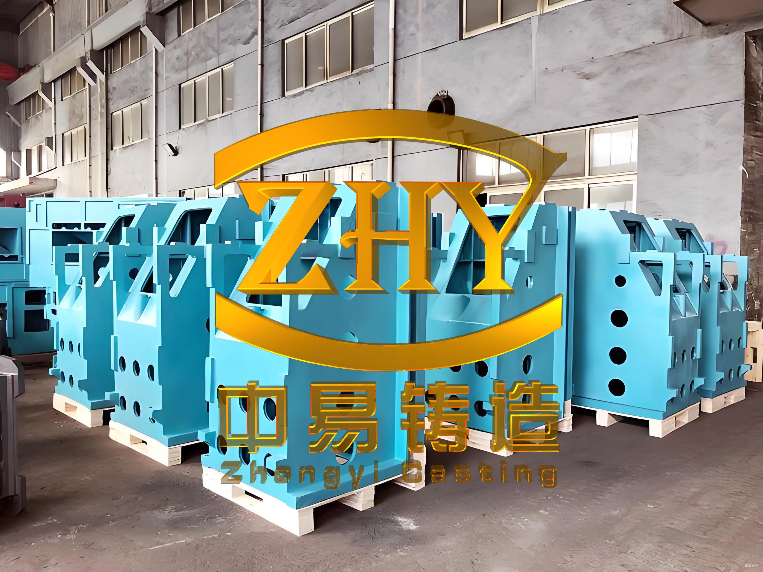
In the manufacturing of high-precision machine tool components, the sliding saddle represents a critical element within machine tool composite machining centers. As a key structural part, machine tool castings like the sliding saddle are typically fabricated from materials such as HT300, with individual weights ranging from over 100 kg to 2,000 kg. These components often exhibit elongated shapes exceeding 1.2 meters to 3 meters in length, featuring guide rail thicknesses greater than 50 mm to 100 mm and main body wall thicknesses including rib plates over 20 mm to 25 mm. The structural complexity of machine tool castings is intentionally designed to enhance strength and rigidity, incorporating numerous small holes and access ports that pose significant challenges during core-making and mold assembly operations. Common defects in these machine tool castings include sand inclusion and sand adhesion, which can compromise the integrity and performance of the final product. The demanding quality requirements for these machine tool castings necessitate continuous improvement in casting methodologies to ensure optimal mechanical properties and dimensional accuracy.
The traditional approach to producing these machine tool castings involved furan resin sand manual molding operations, utilizing either wooden or metal patterns. In our implementation, we employed wooden pattern resin sand processes for manufacturing these machine tool castings. The initial casting process positioned the parting surface at the highest plane of the guide rail base or at the relief surface of the base platform. This configuration placed the entire casting in the lower mold box, with the upper box containing core prints for the clamp openings and internal cavities. The lower box incorporated the complete casting structure with lifting lugs at both ends. During mold assembly, the internal cavity cores were suspended from the upper box, which was then inverted and lowered onto the lower box. This operation required the suspended cores to navigate through various access ports along the side walls of the lower mold, frequently resulting in sand scraping and even core impact against the lower mold surface. The gating system followed a pressurized design with specific area ratios, contributing to relatively high flow velocities at the ingates.
The mathematical representation of the original gating system can be expressed as:
$$ \frac{S_{\text{straight}}}{1} : \frac{S_{\text{horizontal}}}{1.83} : \frac{S_{\text{ingate}}}{0.86} $$
where the flow velocity at the ingate reached approximately 1.63 m/s, calculated using the fundamental fluid flow equation:
$$ v = \frac{Q}{A} $$
where $v$ represents velocity, $Q$ denotes flow rate, and $A$ signifies cross-sectional area.
While this traditional approach offered certain advantages such as reduced risk of metal leakage and improved mold alignment through the lifting lugs, the fundamental drawback of frequent sand inclusion defects during core suspension and assembly operations significantly outweighed these benefits. Attempts to mitigate this issue by increasing clearance between suspended cores and lower mold surfaces to 5 mm or more proved ineffective, instead creating new challenges including excessive flash formation that complicated post-casting cleaning operations and increased the risk of mechanical damage during finishing.
| Parameter | Original Process | Improved Process |
|---|---|---|
| Parting Surface Location | Guide rail base highest plane | Two long guide rail surfaces |
| Casting Position | Entirely in lower box | Entirely in upper box |
| Gating System Type | Pressurized | Unpressurized |
| Gating Ratio (Sstraight:Shorizontal:Singate) | 1:1.83:0.86 | 1:1.55:1.43 |
| Ingate Flow Velocity (m/s) | 1.63 | 0.87 |
| Core-Mold Clearance (mm) | 5+ | 1 |
| Assembly Method | Core suspension | Core placement |
Through systematic analysis and iterative refinement, we developed an optimized casting process that fundamentally addresses the limitations of the traditional approach. The revised methodology repositions the parting plane to the two long guide rail surfaces, effectively transferring the entire casting to the upper mold box. This strategic modification eliminates the problematic core suspension during assembly, instead allowing cores to be positioned directly in the upper box before inversion. The mathematical representation of the improved gating system demonstrates the shift to an unpressurized design:
$$ \frac{S_{\text{straight}}}{1} : \frac{S_{\text{horizontal}}}{1.55} : \frac{S_{\text{ingate}}}{1.43} $$
This revised ratio significantly reduces the ingate flow velocity to approximately 0.87 m/s, enhancing the slag trapping capability of the horizontal gates and promoting cleaner metal entry into the mold cavity. The velocity reduction can be calculated using the continuity equation applied to gating systems:
$$ v_1 A_1 = v_2 A_2 $$
where the subscripts 1 and 2 represent different sections of the gating system.
The improved process maintains the alignment benefits of the original method by extending the guide rail inner sections to create lifting lugs that serve as positioning elements during mold assembly, supplemented by additional box cone定位. The core-to-mold clearance is precisely controlled at 1 mm, effectively eliminating the issues of excessive flash while maintaining sufficient tolerance for assembly operations. During the revised assembly procedure, cores are first placed in the upper box, secured with wires if necessary, before the upper box is inverted and lowered onto the lower box. This sequence allows any dislodged sand to fall away naturally during inversion, with thorough inspection ensuring mold cavity cleanliness before final closure.
The fundamental improvement in the casting process for these machine tool components lies in the transformation from suspended core assembly to placed core assembly, dramatically reducing operational complexity and potential for defects. Additionally, the downward repositioning of the parting plane enables corresponding lowering of the horizontal gate, further enhancing the metallurgical quality of the casting. The strategic implementation of an unpressurized gating system promotes laminar flow conditions and effective slag separation, crucial for producing high-integrity machine tool castings.
The effectiveness of these process improvements is quantitatively demonstrated through statistical analysis of production data, which shows a remarkable reduction in rejection rates from the original 5.5% to below 1.5% for sliding saddle machine tool castings. This significant quality improvement translates directly to enhanced manufacturing efficiency and cost reduction while maintaining the stringent quality standards required for precision machine tool applications. The optimized process has proven particularly beneficial for complex machine tool castings with intricate internal geometries and multiple access ports, where traditional methods frequently encountered operational challenges.
| Performance Indicator | Original Process | Improved Process | Improvement |
|---|---|---|---|
| Rejection Rate (%) | 5.5 | 1.5 | 72.7% reduction |
| Assembly Time (minutes) | 45-60 | 25-35 | Approximately 40% reduction |
| Cleaning Time (minutes) | 30-45 | 15-25 | Approximately 50% reduction |
| Flash-Related Defects (%) | 2.8 | 0.3 | 89.3% reduction |
| Sand Inclusion Defects (%) | 1.9 | 0.2 | 89.5% reduction |
The metallurgical principles underlying the improved process can be further examined through the application of fluid dynamics and solidification theory. The reduction in ingate velocity directly influences the Reynolds number, which characterizes flow regime:
$$ Re = \frac{\rho v D}{\mu} $$
where $Re$ is the Reynolds number, $\rho$ is density, $v$ is velocity, $D$ is hydraulic diameter, and $\mu$ is dynamic viscosity. Lower Reynolds numbers promote laminar flow conditions, reducing turbulence-induced defects in machine tool castings.
Furthermore, the enhanced slag trapping capability of the horizontal gate in the improved system can be analyzed through Stokes’ law, which governs the settling velocity of inclusions:
$$ v_s = \frac{2(\rho_p – \rho_f)gr^2}{9\mu} $$
where $v_s$ is the settling velocity, $\rho_p$ is particle density, $\rho_f$ is fluid density, $g$ is gravitational acceleration, $r$ is particle radius, and $\mu$ is dynamic viscosity. The extended residence time in the enlarged horizontal gate facilitates more effective separation of non-metallic inclusions.
The solidification characteristics of these machine tool castings can be optimized through proper design of the feeding system and cooling conditions. Chvorinov’s rule provides insight into the solidification time relationship:
$$ t = B \left( \frac{V}{A} \right)^n $$
where $t$ is solidification time, $V$ is volume, $A$ is surface area, $B$ is a mold constant, and $n$ is an exponent typically around 2. The modified gating and feeding system in the improved process promotes directional solidification, reducing shrinkage defects in critical sections of the machine tool castings.
From a practical implementation perspective, the revised process has demonstrated excellent reproducibility across multiple production batches of various machine tool castings. The operational simplicity has reduced training requirements for foundry personnel while simultaneously improving process consistency. The reduction in assembly-related defects has decreased the need for extensive repair welding and rework operations, contributing to shorter lead times and improved delivery performance for these critical machine tool components.
The economic impact of the process improvement extends beyond direct quality metrics to include significant reductions in consumable material usage, energy consumption per casting, and environmental footprint through decreased scrap generation. The optimized process represents a sustainable manufacturing approach for producing high-quality machine tool castings that meet the demanding requirements of modern precision machining equipment.
In conclusion, the comprehensive optimization of the casting process for machine tool sliding saddle components has yielded substantial benefits across multiple dimensions including quality, efficiency, and cost-effectiveness. The strategic modifications to parting plane location, gating system design, and assembly methodology have successfully addressed the limitations of traditional approaches while maintaining the advantages of proper mold alignment and metal containment. The significant reduction in rejection rates validates the technical soundness of the improved process, which can be effectively applied to a wide range of machine tool castings with similar structural characteristics and quality requirements. This optimized methodology represents a valuable advancement in the manufacturing of precision components for the machine tool industry, contributing to enhanced performance and reliability of final products.