
In our specialized machine tool manufacturing facility, we frequently encounter challenges with machine tool castings, particularly those involving guide rails. These machine tool castings often exhibit defects such as cracks, chill formation, and structural porosity when produced using single-metal pouring techniques. To address these issues, we developed and implemented a bimetal pouring process, which involves sequentially pouring two different types of molten iron into a single mold to create a composite structure. This approach not only improves the casting processability but also enhances the technical performance of the guide rail materials, leading to significant economic benefits. The following sections detail our methodology, experimental procedures, results, and conclusions, with an emphasis on the application to machine tool castings.
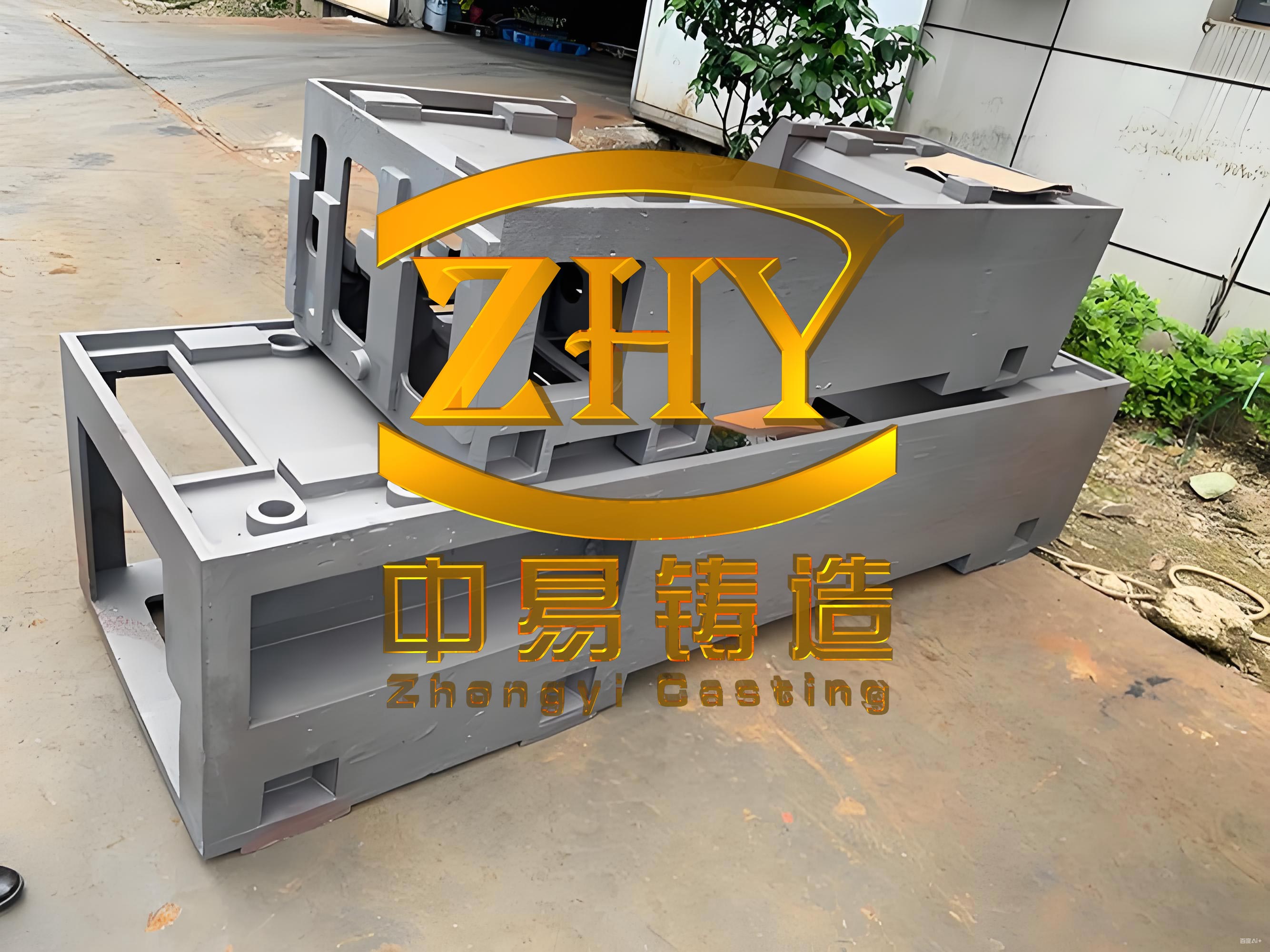
The bimetal pouring process was specifically designed for complex machine tool castings like slide seats, where the guide rail sections require high hardness and wear resistance, while the base sections need good machinability and reduced stress concentration. We utilized two distinct iron grades: a high-strength inoculated iron for the guide rails and a standard gray iron for the base. This combination mitigates common defects in machine tool castings, such as cracking at thin-thick wall junctions and localized hardness variations.
To implement bimetal pouring, we designed two separate gating systems for the mold. The first gating system (System 1) was responsible for filling the guide rail section with high-strength iron, while the second (System 2) introduced the base iron. System 1 employed a closed gating design with a cross-sectional area ratio of sprue to runner to ingate of approximately 1:1.5:1.2, ensuring smooth filling from the bottom of the guide rail. To prevent slag inclusion, we incorporated a filter mesh at the junction of the pouring basin and sprue, along with a slag trap in the runner. For larger machine tool castings, we used a large堵塞-type pouring basin to facilitate simultaneous pouring from two overhead cranes, as the casting length required synchronized operation.
System 2 was designed as a closed-open gating system with a cross-sectional ratio of sprue to runner to ingate of about 1:1.8:1.5. The ingates were positioned at a height of 40–50 mm above the guide rail section, allowing the base iron to fill the upper regions without excessive mixing. This setup minimized the mixing zone between the two irons, which is critical for maintaining the desired material properties in machine tool castings. Test blocks were also cast alongside the main casting to evaluate mechanical properties and microstructure variations along the height, replicating the guide rail’s dimensions and gating conditions.
| Gating System | Type | Cross-Sectional Ratio (Sprue:Runner:Ingate) | Ingate Position | Purpose |
|---|---|---|---|---|
| System 1 | Closed | 1:1.5:1.2 | Bottom of guide rail | Fill guide rail with high-strength iron |
| System 2 | Closed-Open | 1:1.8:1.5 | 40–50 mm above guide rail | Fill base with standard iron |
Material selection was based on the functional requirements of the machine tool castings. The guide rail section used a high-strength inoculated iron equivalent to Grade HT300, with a target pearlite content exceeding 90% to ensure high hardness after heat treatment. The base section employed Grade HT200 iron, which offers adequate strength and low casting stress, reducing the risk of cracks in thin-walled areas. The chemical composition for the guide rail iron was carefully controlled, with key elements including Carbon (C) at 3.2–3.4%, Silicon (Si) at 1.8–2.1%, Manganese (Mn) at 0.8–1.0%, Phosphorus (P) below 0.15%, and Sulfur (S) below 0.12%. Alloying elements such as Chromium (Cr) and Molybdenum (Mo) were added to enhance hardenability, and inoculation was performed using ferrosilicon.
Melting was carried out in a central blast cupola for the base iron and a medium-frequency induction furnace for the alloyed iron. The guide rail iron was produced by mixing cupola-melted base iron with induction-furnace-melted alloyed iron, followed by inoculation. The total weight of iron required for the guide rail and test blocks was approximately 600 kg, with strict control over the mixing ratio to maintain compositional accuracy within ±2%.
| Iron Grade | C (%) | Si (%) | Mn (%) | P (%) | S (%) | Alloying Elements |
|---|---|---|---|---|---|---|
| Guide Rail (HT300 Equivalent) | 3.2–3.4 | 1.8–2.1 | 0.8–1.0 | <0.15 | <0.12 | Cr, Mo |
| Base (HT200) | 3.3–3.5 | 2.0–2.3 | 0.6–0.8 | <0.15 | <0.12 | None |
The pouring process was critical for achieving a successful bimetal structure in machine tool castings. We controlled three key parameters: iron weight, pouring temperature, and simultaneous pouring time. System 1 was initiated first to fill the guide rail section. When the molten iron level reached 30–40 mm above the guide rail, System 2 commenced pouring the base iron. The simultaneous pouring time was maintained at 8–12 seconds, depending on the casting size, to prevent cold shuts. The pouring temperature for the guide rail iron was kept relatively low, near the solidification point, to minimize mixing with the base iron. In contrast, the base iron was poured at a higher temperature to ensure fluidity in thin sections. The relationship between pouring temperature and mixing zone height can be expressed using the following empirical formula:
$$ T_g = T_s + (50 \text{ to } 100) \, ^\circ\text{C} $$
where \( T_g \) is the pouring temperature for the guide rail iron, and \( T_s \) is the solidification temperature of the iron. This ensures that the guide rail iron begins to form a mushy zone upon the base iron’s entry, limiting penetration.
During the experiments, we poured multiple slide seat castings and test blocks. One casting was produced with single-metal HT300 iron for comparison. The guide rail iron was tapped from the cupola at temperatures above 1420°C, mixed with alloyed iron in the ladle, inoculated, and then transferred to the pouring basin of System 1. The base iron was prepared separately and poured via System 2. Temperature measurements were taken before pouring to adhere to the specified ranges.
Results analysis focused on the mixing zone, hardness distribution, and metallographic structure. Samples were taken from vertical test blocks at 20 mm intervals for chemical analysis and hardness testing. The mixing zone height \( H_m \) was found to be influenced by the pouring temperature \( T_g \) and simultaneous pouring time \( t_s \). For instance, when \( T_g \) was high (e.g., 1380°C) and \( t_s \) was long, \( H_m \) extended to the bottom of the guide rail, as shown by the carbon concentration curve. Conversely, with \( T_g \) at 1320°C and \( t_s \) at 8 seconds, \( H_m \) was limited to about 20 mm. The relationship can be modeled as:
$$ H_m = k \cdot (T_g – T_s) \cdot t_s $$
where \( k \) is a constant dependent on the gating design and iron properties. This highlights the importance of tight parameter control in machine tool castings.
| Casting Type | Pearlite Content (%) | As-Cast Hardness (HB) | Hardness After Quenching (HS) | Mixing Zone Height (mm) |
|---|---|---|---|---|
| Single-Metal (HT300) | 75–80 | 180–200 | 40–45 | N/A |
| Bimetal (Optimal Parameters) | >90 | 220–240 | 50–55 | 15–20 |
| Bimetal (High Mixing) | 70–85 | 190–220 | 45–50 | 40–60 |
Hardness tests revealed that single-metal castings had uniform but lower hardness, whereas bimetal castings with optimal parameters achieved higher and more consistent hardness. The as-cast hardness of the guide rail section in bimetal machine tool castings reached 220–240 HB, compared to 180–200 HB for single-metal versions. After high-frequency quenching, the hardness values improved significantly, with Shore hardness (HS) readings of 50–55 for bimetal castings versus 40–45 for single-metal. The correlation between pearlite content \( P_c \) and quenched hardness \( H_q \) can be approximated by the linear equation:
$$ H_q = a \cdot P_c + b $$
where \( a \) and \( b \) are constants derived from experimental data. For our machine tool castings, \( a \approx 0.3 \) and \( b \approx 25 \), indicating that a 10% increase in pearlite content raises quenched hardness by approximately 3 HS points.
Metallographic examination of test blocks showed that single-metal castings had a microstructure comprising 75–80% pearlite and 15–20% ferrite, leading to a mixed martensite-ferrite structure after quenching. In contrast, bimetal castings with controlled parameters exhibited over 90% pearlite, resulting in a fully martensitic structure upon quenching. This microstructure contributes to the superior hardness and wear resistance required for machine tool castings. If parameters were suboptimal, ferrite formation increased, reducing hardness uniformity.
In production applications, the bimetal-poured slide seats demonstrated excellent performance, with quenched hardness values ranging from 50 to 55 HS along the guide rail. Measurements taken every 100 mm confirmed consistency, positioning this technology as a leading solution in the industry. Economically, bimetal pouring reduces costs by approximately 50 USD per ton compared to single-metal HT300 pouring, due to material savings and reduced defect rates.
In conclusion, the bimetal pouring process for machine tool castings effectively addresses defects like cracks and chill formation while enhancing mechanical properties. Key factors include the design of segregated gating systems, precise control of iron composition, and strict adherence to pouring parameters. The pouring temperature for the guide rail iron should be maintained at \( T_s + 50 \) to \( 100^\circ\text{C} \), and simultaneous pouring time should be 8–12 seconds. The hardness after quenching is directly proportional to the pearlite content, underscoring the importance of microstructure control. This method not only improves the quality of machine tool castings but also offers substantial economic advantages, making it a viable approach for industrial adoption.