
In my extensive experience with full mold casting for large machine tool castings, I have observed that this method offers significant advantages in producing complex geometries, but it requires meticulous process design to avoid defects such as porosity, shrinkage, and deformation. The use of expanded polystyrene (EPS) patterns in full mold casting, particularly for machine tool castings like beds, columns, and tables, demands careful consideration of parameters like gating systems, pouring temperatures, and sand properties. This article delves into the key aspects of process design for large machine tool castings, drawing from practical applications to highlight best practices and solutions to common challenges. Throughout this discussion, I will emphasize the importance of adapting techniques to specific casting requirements to achieve high-quality machine tool castings.
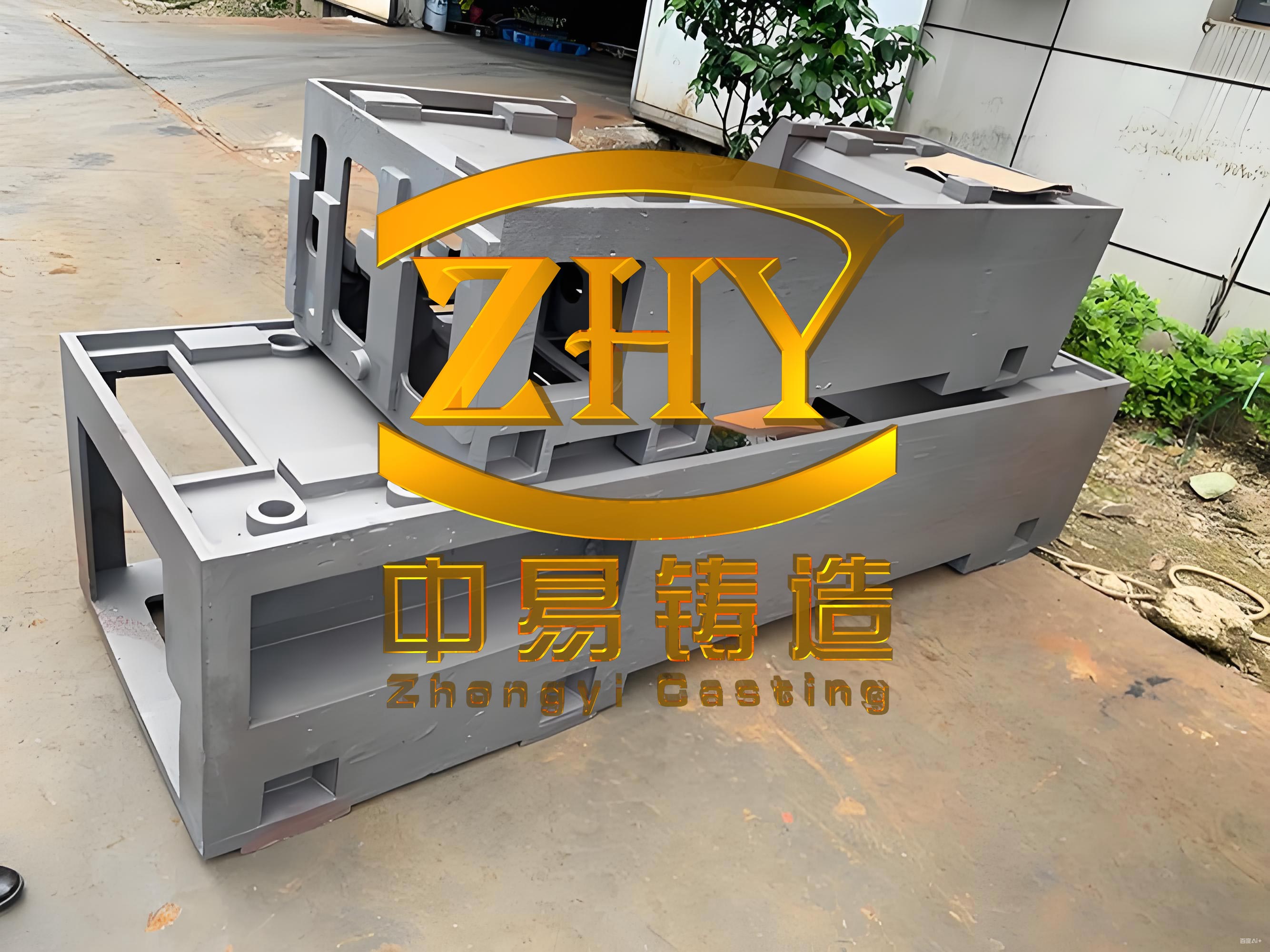
Large machine tool castings are critical components in industrial machinery, often characterized by their substantial size, weight, and intricate structures. For instance, machine tool castings such as beds and columns can exceed 10 meters in length and weigh over 20 tons, making them prone to issues like gas entrapment and dimensional inaccuracies if not handled properly. In full mold casting, the EPS pattern decomposes upon contact with molten metal, releasing gases that must be managed through effective venting and sand permeability. Below, I present a table summarizing typical large machine tool castings I have worked with, highlighting their dimensions and key features.
| Component Type | Material | Dimensions (Length × Width × Height, mm) | Weight (t) | Key Challenges |
|---|---|---|---|---|
| Bed for Milling Machine | HT250 | 7700 × 1900 × 703 | 18.0 | Gas porosity, deformation |
| Column for Planer | HT250 | 4020 × 2000 × 950 | 11.0 | Shrinkage, sand inclusion |
| Bed for Grinding Machine | Alloy Cast Iron | 12000 × 2000 × 710 | 23.0 | Longitudinal distortion, cold shuts |
| Headstock Base | HT250 | 2700 × 2100 × 750 | 18.5 | Risering, gating design |
The design of the casting process begins with selecting the parting plane, which for machine tool castings is typically oriented with the导轨 surface downward to minimize defects. In full mold casting, the EPS pattern’s low shrinkage allows for simplified pattern making, but the linear contraction of gray iron must be accounted for using a standard value, such as 1%. The machining allowances for large machine tool castings are generally larger than in conventional wood pattern casting to accommodate potential distortions. I have found that the following table provides reliable guidelines for machining allowances based on casting size and weight.
| Casting Weight (t) | Upper Surface Allowance (mm) | Lower Surface Allowance (mm) | Side Allowance (mm) | Guideway Allowance (mm) | Bore Radius Allowance (mm) |
|---|---|---|---|---|---|
| 5-10 | 10-15 | 8-10 | 10 | 10 | 6 |
| 10-15 | 10-15 | 10-12 | 10 | 10-15 | 7 |
| 15-25 | 15-20 | 10-15 | 10-15 | 15-20 | 8 |
When it comes to molding methods, pit molding is often preferred for large machine tool castings due to cost and lead-time considerations. For example, a bed casting measuring 12m in length would require a flask weighing over 12 tons, which is impractical for small batches. In pit molding, proper ventilation is crucial to handle the gases from EPS decomposition. I typically use a layered approach with dry sand, coke, and straw ropes connected to exhaust pipes, as illustrated by the following setup: a base layer of dry sand, followed by coke for permeability, and vent pipes leading to the surface. The sand-to-metal ratio in pit molding is higher, around 3:1, compared to 2.5:1 in flask molding, to ensure adequate strength and gas escape.
The choice of sand is vital; I use cold-set furan resin sand with reclaimed sand regeneration to achieve a final strength of 0.5-0.8 MPa and permeability of 300-500. The sand compaction must be uniform to avoid weak spots that could lead to runouts or sand inclusions. For large machine tool castings, I recommend filling sand from the ends toward the center to prevent voids. The minimum sand thickness around the pattern, known as the sand allowance, should be 250-300 mm at the bottom, 300-350 mm on the sides, and 200-250 mm on top for pit molding, as detailed in the table below.
| Molding Method | Bottom Allowance (mm) | Side Allowance (mm) | Top Allowance (mm) | Sand-to-Metal Ratio |
|---|---|---|---|---|
| Pit Molding | 250-300 | 300-350 | 200-250 | 3:1 |
| Flask Molding | 200-250 | 150-200 | 150-200 | 2.5:1 |
The gating system design is a cornerstone of successful full mold casting for machine tool castings. I often employ multiple sprue systems—two or more for castings over 5 tons—to ensure even filling. The cross-sectional areas are proportioned as follows: the total sprue area (∑F_sprue) to total runner area (∑F_runner) to total ingate area (∑F_ingate) is set at 1:1.5:2. This can be expressed mathematically as:
$$ \frac{\sum F_{\text{sprue}}}{\sum F_{\text{runner}}} : \frac{\sum F_{\text{runner}}}{\sum F_{\text{ingate}}} = 1 : 1.5 : 2 $$
For bottom gating, I space ingates 80-100 mm apart, and for castings taller than 350 mm, multiple layers of ingates are used. Hollow ceramic tubes are ideal for sprues to reduce turbulence. Regarding risering, while some sources suggest minimal risers for high carbon equivalent irons, I find that blind risers are necessary for large machine tool castings to compensate for shrinkage in low carbon equivalent conditions (e.g., 3.4-3.8% CE). The size and number of risers depend on the casting weight; for instance, a 20-ton casting might use risers with dimensions of 100 mm × 150 mm. Additionally, I incorporate vent risers of 25-35 mm diameter, spaced 1-1.5 m apart, to release gases.
Chills are essential for controlling solidification in thick sections like guideways. I use external chills with a thickness of one-third to one-quarter the thermal modulus of the section. For hard-to-reach areas, internal chills can be inserted directly into the EPS pattern. Coating application is another critical step; I apply a water-based coating first, followed by an alcohol-based coating, with a total thickness of 1.5-2.5 mm after drying at 50-60°C for 8-12 hours. For particularly thick sections, a zircon flour coating can prevent burn-on defects.
Pouring parameters must be optimized to avoid defects. Based on my experience, the pouring temperature and speed vary with casting weight and wall thickness, as summarized in the table below. For example, a 10-15 ton machine tool casting with an average wall thickness of 40-60 mm should be poured at 1360-1380°C, with a filling rate of 2.5-3.5 tons per minute.
| Casting Weight (t) | Average Wall Thickness (mm) | Pouring Temperature (°C) | Filling Rate (t/min) | Number of Sprues |
|---|---|---|---|---|
| 0.5-2.0 | 20-30 | 1390-1410 | 2.5-3.0 | 1 |
| 5-10 | 30-40 | 1370-1390 | 2.5-3.0 | 2 |
| 10-20 | 40-60 | 1360-1380 | 2.5-3.5 | 2-4 |
| 20-35 | 45-65 | 1350-1370 | 2.5-3.5 | 3-5 |
During pouring, simultaneous filling of all sprues is critical to prevent back-pressure issues. I recommend using ladles with sufficient head pressure to maintain a steady flow, and operators should monitor the basin to adjust ladle height as needed. Post-pouring, castings should be left in the mold for extended periods—up to 100 hours for a 20-ton bed—to reduce residual stresses and minimize distortion, with knockout temperatures below 200°C.
Common defects in large machine tool castings include shrinkage porosity, deformation, and core lift. For shrinkage in thick upper sections, I address this by positioning ingates to direct hot metal to these areas, using chills, and slightly increasing the carbon equivalent where possible. Deformation control is challenging; for castings over 6 meters, I apply a reverse camber of 0.5‰ to 1.5‰ by shaping the sand core or pit bottom. Weighting the EPS pattern during molding can help maintain this camber, as shown in practice by placing weights on the pattern to match the sand contour. The relationship for camber can be expressed as:
$$ \text{Camber} = L \times \left( \frac{0.5}{1000} \text{ to } \frac{1.5}{1000} \right) $$
where L is the casting length in mm. Additionally, increasing machining allowances or extending mold cooling times can mitigate dimensional errors.
Core lift, or floating cores, occurs in enclosed structures like columns, where molten metal buoyancy displaces the core. To prevent this, I reinforce cores with strong, rigid chaplets and use clamping devices on non-machined surfaces. This ensures uniform wall thickness and avoids leakage paths. In one instance, for a machine tool casting with internal cavities, proper core anchoring eliminated upper wall thinning and porosity.
In conclusion, the full mold casting process for large machine tool castings requires a holistic approach that balances theoretical principles with practical adaptations. Through iterative improvements, I have refined parameters such as gating ratios, sand properties, and pouring techniques to achieve defect-free machine tool castings. The key lies in customizing the process for each casting’s geometry and material, leveraging experiences to overcome challenges like gas management and distortion. As the demand for high-precision machine tool castings grows, continued innovation in full mold casting will be essential for advancing industrial manufacturing capabilities.