
As a specialist in foundry engineering, I have extensively studied the challenges associated with improving the surface quality of machine tool castings, particularly for worktable components. Machine tool castings are critical in industrial applications, where not only internal integrity but also external appearance plays a vital role in product acceptance and performance. In this article, I will share my insights and experiences in developing advanced foundry processes that eliminate surface defects, such as sand nail marks, without compromising structural integrity. By leveraging the inherent characteristics of machine tool castings and optimizing existing models and tooling, we can achieve superior surface finishes. This discussion will include detailed calculations, formulas, and tables to summarize key aspects, emphasizing the importance of machine tool casting and machine tool castings in modern manufacturing.
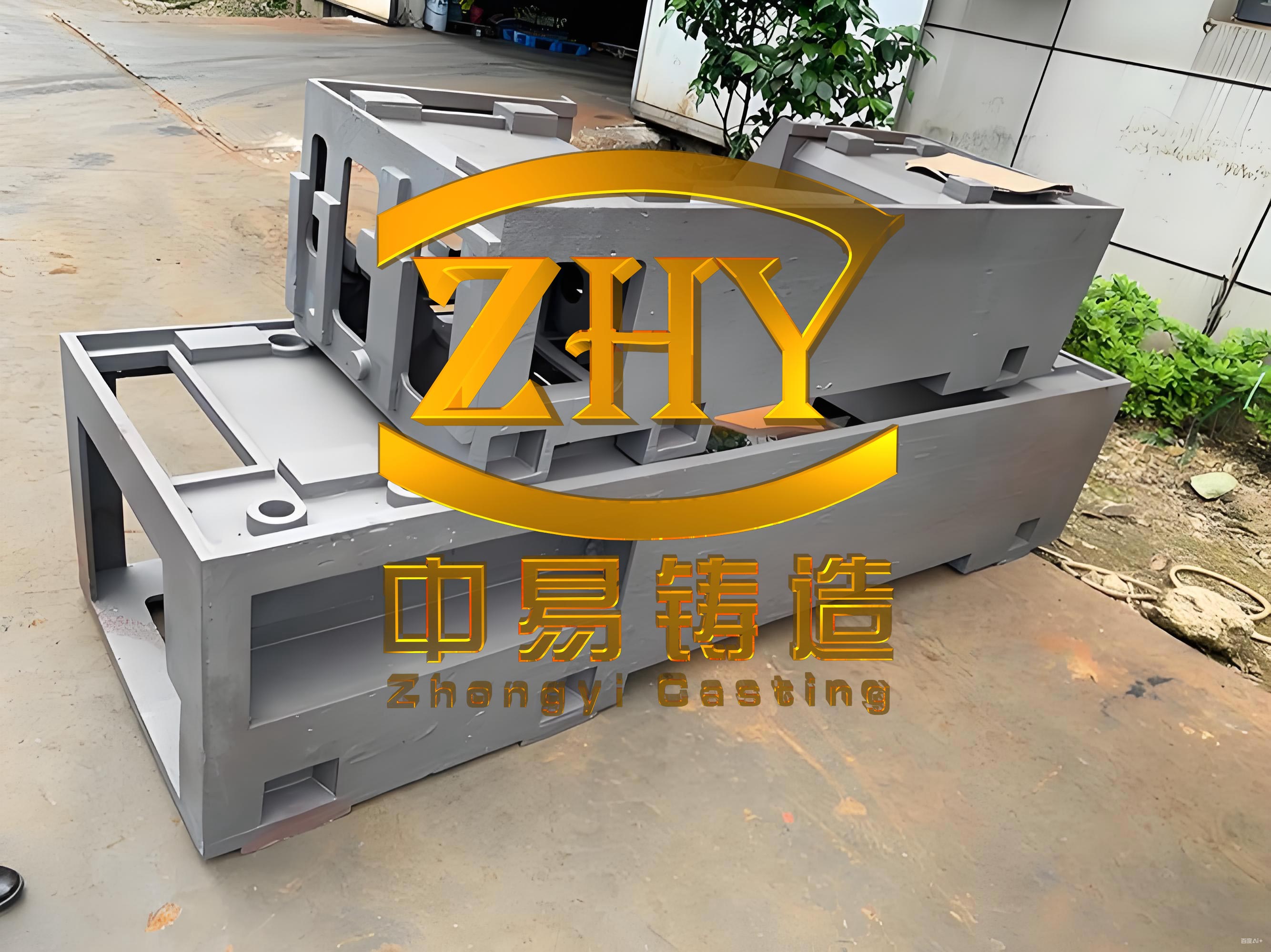
Machine tool castings, especially worktable components, are fundamental to the precision and durability of machine tools. These castings often feature complex geometries, such as those with large dimensions and intricate cores, which pose significant challenges in maintaining surface quality. For instance, a typical worktable casting might have a flange diameter of 1500 mm and a mass of approximately 1200 kg, made from materials like HT250. The conventional foundry process involves using sand nails to secure cores within the mold, leading to unsightly white spots on the surface after casting. These defects, while not affecting functional performance, severely impact the aesthetic appeal of machine tool castings, necessitating special measures for export-quality products. In my work, I have focused on refining these processes to enhance the overall quality of machine tool castings.
The original foundry process for machine tool castings relied heavily on sand nails to fix large sand cores in place. This method, while effective for core stability, resulted in numerous sand nail imprints on the casting surface, appearing as white spots after processing. Specifically, for a worktable casting, up to 20 sand nails were used, embedding them within the mold and causing these defects to become encapsulated in the final product. The pouring process involved resin-coated sand for core-making, with a shrinkage allowance of 1%, and required precise machining allowances on various surfaces. The mold was composed of green sand for the main body and furan resin sand for cores, with a hardening time controlled to ensure proper strength. However, this approach led to significant rework and dissatisfaction in high-stakes applications, highlighting the need for improved methods in producing machine tool castings.
To address these issues, I proposed a novel foundry process that eliminates the use of sand nails altogether. This innovative approach utilizes a steel ring sand core plate and dedicated steel columns to support the sand cores during casting. By integrating these elements into the mold design, we can prevent any surface marks while maintaining core stability. The key to this method lies in modifying the casting structure to include additional reinforcements, such as small raised platforms, which enhance the overall strength of the machine tool casting. Moreover, the process demands strict adherence to foundry principles, ensuring adequate sand compaction and core rigidity to prevent deformation or collapse. This not only improves the surface quality of machine tool castings but also streamlines production by reducing post-casting corrections.
In designing the steel ring sand core plate, I conducted thorough calculations to ensure it could withstand the loads during casting. The sand core’s volume and mass were determined based on the geometry of the worktable casting. For example, the total volume of the flange and related sections was calculated by subtracting the volume of the shaft hole and other non-core areas from the overall casting volume. The mass of the sand core was then derived using the density of the molding sand. Let me illustrate this with a formula for the sand core volume \( V_{\text{core}} \):
$$ V_{\text{core}} = V_{\text{total}} – V_{\text{shaft}} – V_{\text{actual}} $$
Where \( V_{\text{total}} \) is the total volume of the casting, \( V_{\text{shaft}} \) is the volume of the shaft hole, and \( V_{\text{actual}} \) is the volume of solid sections. Assuming a worktable with a flange diameter of 1500 mm and a height of 200 mm, the total volume can be approximated as a cylinder, leading to:
$$ V_{\text{total}} = \pi \times \left( \frac{1500}{2} \right)^2 \times 200 $$
For a shaft hole diameter of 300 mm, the volume subtracted is:
$$ V_{\text{shaft}} = \pi \times \left( \frac{300}{2} \right)^2 \times 200 $$
The actual volume depends on specific design features, but in practice, the core volume for such a machine tool casting might be around 0.25 m³. Given the density of self-hardening sand (\( \rho \approx 1.6 \, \text{g/cm}^3 \)), the mass \( m_{\text{core}} \) is:
$$ m_{\text{core}} = \rho \times V_{\text{core}} = 1.6 \times 10^3 \, \text{kg/m}^3 \times 0.25 \, \text{m}^3 = 400 \, \text{kg} $$
This mass must be supported by the steel ring and columns without causing deformation. The steel ring was designed as an annular plate with an inner diameter of 1400 mm and an outer diameter of 1520 mm, made from Q235A steel. To calculate the bending stress on the ring, I applied the formula for a uniformly loaded circular plate. The maximum bending moment \( M_{\text{max}} \) at the center of a simply supported ring can be expressed as:
$$ M_{\text{max}} = \frac{w \times r^2}{8} $$
Where \( w \) is the distributed load per unit area, and \( r \) is the radius. For a load equivalent to the sand core mass distributed over the ring’s area, \( w = \frac{m_{\text{core}} \times g}{A_{\text{ring}}} \), with \( g = 9.81 \, \text{m/s}^2 \) and \( A_{\text{ring}} \) as the surface area of the ring. Using an average radius of 730 mm, the load calculation yields a bending stress that must be below the allowable stress for Q235A steel (approximately 160 MPa). The cross-sectional dimensions of the ring were optimized to a thickness of 30 mm, ensuring sufficient strength while minimizing material use.
For the dedicated steel columns, I designed them to bear the load of the sand cores without sinking into the mold. Each column, made from Q235A steel, has a diameter of 50 mm and a height of 150 mm, with enlarged ends to fit into refractory sleeves. The compressive stress on each column was calculated based on the total load divided by the number of columns. Assuming 4 columns supporting the 400 kg core mass, the load per column \( F_{\text{column}} \) is:
$$ F_{\text{column}} = \frac{m_{\text{core}} \times g}{4} = \frac{400 \times 9.81}{4} = 981 \, \text{N} $$
The cross-sectional area \( A_{\text{column}} = \pi \times \left( \frac{50}{2} \right)^2 = 1963.5 \, \text{mm}^2 \), so the compressive stress \( \sigma_{\text{column}} \) is:
$$ \sigma_{\text{column}} = \frac{F_{\text{column}}}{A_{\text{column}}} = \frac{981}{1963.5 \times 10^{-6}} \approx 0.5 \, \text{MPa} $$
This is well below the compressive strength of Q235A steel (around 235 MPa) and the refractory material’s strength, ensuring stability during pouring. Additionally, the use of refractory sleeves with a diameter of 60 mm and a height of 20 mm provides a secure fit, preventing any displacement under high temperatures. The pouring temperature was controlled between 1380°C and 1420°C, with a fast pouring time to minimize thermal stresses, further protecting the surface quality of the machine tool casting.
To summarize the design parameters, I have compiled key data into tables that highlight the calculations and specifications for the improved foundry process. These tables serve as a quick reference for implementing similar enhancements in other machine tool castings.
| Parameter | Value | Unit |
|---|---|---|
| Total Flange Volume | 0.35 | m³ |
| Shaft Hole Volume | 0.14 | m³ |
| Core Volume | 0.25 | m³ |
| Sand Density | 1600 | kg/m³ |
| Core Mass | 400 | kg |
| Component | Dimension | Material | Allowable Stress |
|---|---|---|---|
| Steel Ring (Inner Diameter) | 1400 mm | Q235A | 160 MPa |
| Steel Ring (Outer Diameter) | 1520 mm | Q235A | 160 MPa |
| Steel Ring Thickness | 30 mm | Q235A | 160 MPa |
| Steel Column Diameter | 50 mm | Q235A | 235 MPa |
| Steel Column Height | 150 mm | Q235A | 235 MPa |
| Refractory Sleeve Diameter | 60 mm | Refractory Material | 15 MPa |
The implementation of this new process has yielded remarkable results in the production of machine tool castings. By eliminating sand nails, we have completely removed the white spot defects on the worktable surfaces, resulting in a smooth, aesthetically pleasing finish. This not only meets the high standards for export products but also reduces the need for additional machining and rework, saving time and resources. In trials involving over 50 castings, the dimensions and properties consistently met design requirements, with no signs of core displacement or surface imperfections. The streamlined molding and pouring operations have enhanced productivity, as the steel ring and columns integrate seamlessly with existing patterns and tooling, minimizing disruptions to regular production schedules.
Furthermore, the improved foundry process has positive implications for the overall lifecycle of machine tool castings. By preventing surface defects, we reduce the risk of stress concentration points that could lead to fatigue or failure in service. This is particularly important for machine tool castings used in high-precision applications, where even minor surface irregularities can affect performance. The use of standardized components, such as the steel ring and columns, allows for easy replication across different casting designs, promoting scalability and consistency in manufacturing. As a result, this approach not only enhances the quality of individual machine tool castings but also contributes to the advancement of foundry technology as a whole.
In conclusion, the development of advanced foundry processes for machine tool castings has proven essential in achieving superior surface quality. Through careful design and calculation, we have successfully replaced traditional sand nails with steel supports, eliminating defects and improving the visual appeal of worktable components. The formulas and tables provided here offer a practical framework for others in the industry to adopt similar methods. As we continue to innovate, the focus on machine tool casting and machine tool castings will remain central to driving improvements in manufacturing efficiency and product excellence. This experience underscores the importance of integrating engineering principles with practical foundry techniques to overcome challenges and deliver high-quality results.