
In my extensive experience within the foundry industry, the design and production of large, intricate machine tool castings present significant challenges due to their structural complexity and stringent quality requirements. The sensitivity of these machine tool castings to various casting process factors varies considerably depending on their specific geometries, with the gating system design playing a pivotal role in ensuring consistent quality and stability. Traditional methods for producing machine tool castings, such as using green sand, dry sand molds, two-part or three-part flasks, or split-box molding, often employ stepped gating, bottom gating, or two-end pouring systems. However, the effectiveness of these approaches differs based on individual production conditions and the unique structural characteristics of the machine tool castings. Through years of practice, we have found that split-box molding combined with bottom-pouring gating systems, including bottom-side gating, yields highly successful outcomes for many machine tool castings. In this discussion, I will analyze two representative cases of machine tool bed castings to share insights and lessons learned, emphasizing the iterative nature of process optimization for machine tool castings.
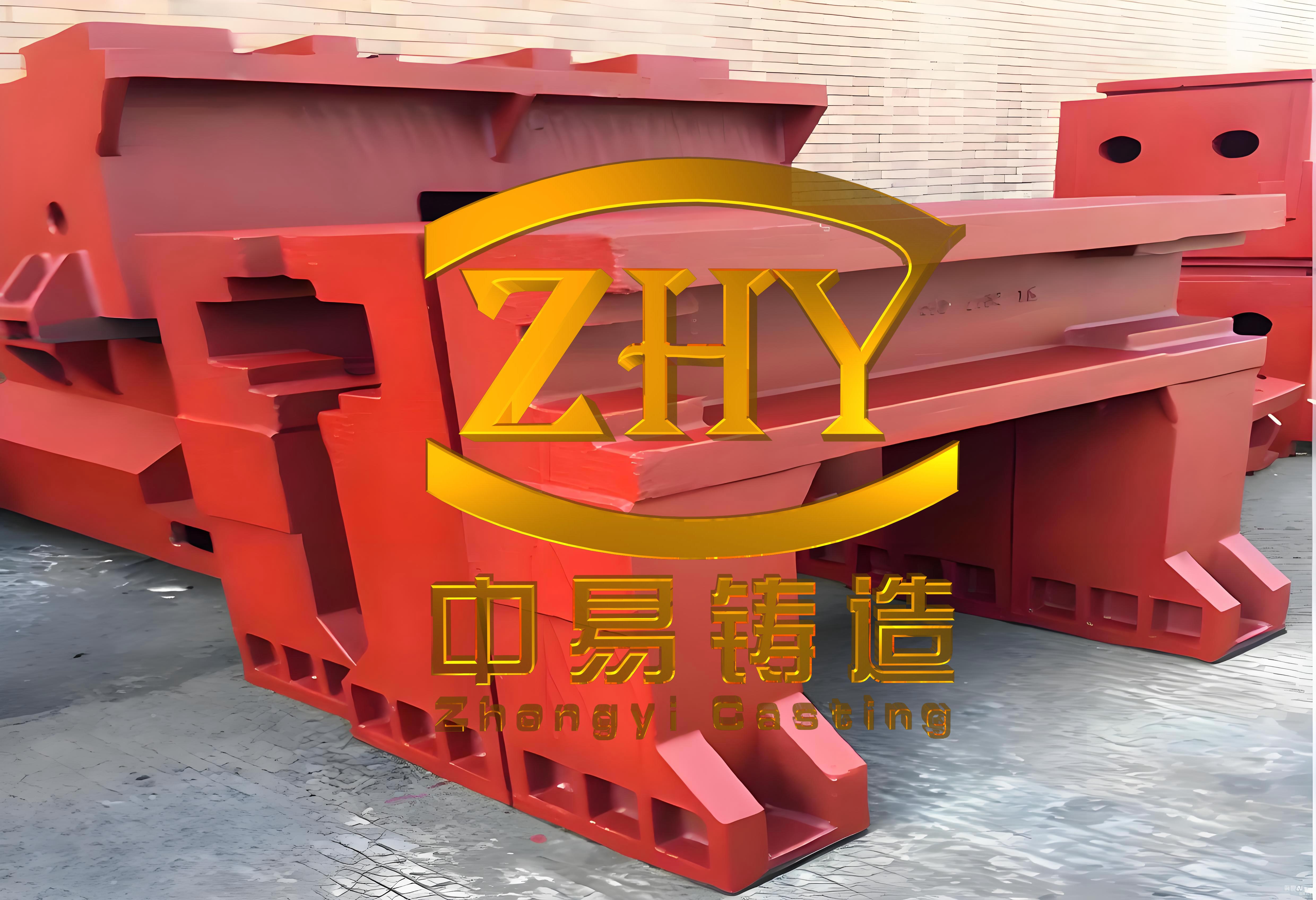
The first case involves a large boring machine bed, a quintessential example of complex machine tool castings. This machine tool casting had overall dimensions of approximately 3000 mm in length, 2000 mm in width, and 1000 mm in height, with a rough weight nearing 10,000 kg. The material specification was HT300 gray iron, and the primary guideways required a hardness of 190-220 HB. The structure featured wide primary guideways flanked by auxiliary guideways on both sides, with the maximum guideway thickness reaching 80 mm. Our initial process design utilized clay-bonded sand, dry sand molds, and split-box molding. The gating system was an open-type bottom-side gating arrangement, where molten metal was introduced from the lower outer sides of the two primary guideways via horizontal runners. Additionally, graphite chills were uniformly distributed across the primary guideway surfaces to control solidification. We produced three initial castings using this scheme for machine tool castings. After rough machining, minor porosity and slag inclusions were detected on the auxiliary guideway surfaces, while the primary guideways remained defect-free. Analysis revealed that as the metal level rose to a certain height, it cascaded sideways toward the auxiliary guideways, resulting in a significant temperature drop that fostered gas and slag entrapment. To address this, we incorporated a chill water groove measuring 10 mm in width and 100 mm in thickness along the outer side below the auxiliary guideways. This modification served to trap the initial, cooler metal flow, effectively eliminating the defects and underscoring the importance of thermal management in machine tool castings.
To quantify the thermal dynamics, we applied Chvorinov’s rule to estimate solidification times for different sections of the machine tool casting. The solidification time \( t \) is given by:
$$ t = C \left( \frac{V}{A} \right)^2 $$
where \( V \) is the volume of the casting section, \( A \) is its surface area, and \( C \) is a mold constant dependent on the sand properties. For the auxiliary guideway region, the modulus \( M = V/A \) was calculated to be approximately 0.02 m, leading to a solidification time of about 120 seconds, whereas the primary guideways, with a modulus of 0.03 m, solidified in around 270 seconds. This disparity highlighted the need for targeted cooling in thinner sections to prevent defects in machine tool castings. Furthermore, the flow rate \( Q \) in the gating system was determined using the equation:
$$ Q = A_g \cdot v_g $$
where \( A_g \) is the cross-sectional area of the ingate and \( v_g \) is the flow velocity, derived from Bernoulli’s principle as \( v_g = \sqrt{2gh} \), with \( h \) being the metallostatic head height. For this machine tool casting, the initial gating design had a total ingate area of 15 cm², resulting in a flow rate of 12 kg/s, which was adjusted to 10 kg/s post-modification to reduce turbulence. The table below summarizes key parameters for this machine tool casting instance, illustrating the interplay between geometry, process, and quality in machine tool castings.
| Parameter | Initial Value | Modified Value | Impact on Defects |
|---|---|---|---|
| Gating System Type | Bottom-Side Gating | Bottom-Side Gating with Chill Groove | Reduced slag and porosity on auxiliary guideways |
| Ingate Cross-Sectional Area (cm²) | 15 | 12 | Decreased flow velocity, minimizing turbulence |
| Metallostatic Head Height (m) | 0.8 | 0.8 | Maintained consistent metal pressure |
| Solidification Modulus – Primary Guideway (m) | 0.03 | 0.03 | Longer solidification time required chills |
| Solidification Modulus – Auxiliary Guideway (m) | 0.02 | 0.02 | Faster solidification prone to defects without modification |
| Defect Rate (%) | 15 | ~2 | Significant improvement post-optimization |
Despite these improvements, challenges persisted in subsequent production runs of machine tool castings. In particular, irregularities in the ingate alignment—some tilting inward and upward—led to localized metal splashing and premature solidification within the ingates. This caused blockages and resulted in scattered porosity clusters and slag inclusions on the primary guideway surfaces and their opposing faces. Upon investigation, we observed that metal entering through horizontally oriented ingates would flow forward, impact the mold wall, and reverse direction, sometimes flowing back into upward-tilted ingates. This backflow trapped slag and gas in dead zones along the guideway sides, exacerbating defects in machine tool castings. The kinetic energy of the initial metal stream, given by \( E_k = \frac{1}{2} \rho v^2 \), where \( \rho \) is the metal density and \( v \) is the velocity, contributed to splashing when ingates were misaligned. To resolve this, we transitioned to a bottom-shower gating system, where ingates were directed precisely toward these dead zones. This change facilitated better slag flotation and gas expulsion, reducing the defect rate from over 15% to below 5% for machine tool castings. The effectiveness of this adjustment can be modeled using the Reynolds number \( Re \) for flow characterization:
$$ Re = \frac{\rho v D}{\mu} $$
where \( D \) is the hydraulic diameter of the ingate and \( \mu \) is the dynamic viscosity of the molten iron. By reducing \( Re \) from 5000 (turbulent) to 3000 (transitional), we minimized oxide formation and gas entrainment in machine tool castings.
The second case study focuses on a guideway grinding machine frame, another complex machine tool casting with dimensions of 4000 mm in length, 1500 mm in width, and 1200 mm in height, weighing approximately 5000 kg. This machine tool casting was characterized by upper and lower guideways on both sides, a high pouring height of 1200 mm, and a propensity for porosity and slag defects on the guideways. While higher pouring temperatures could reduce such defects, they risked causing shrinkage cavities in thicker sections of the guideways. Our analysis of the structure highlighted similarities and differences with standard machine tool castings; specifically, the poor slag and gas venting conditions at the mid-height of the guideways, around 600 mm from the bottom, posed unique challenges. Initially, we adopted a double split-box molding process with two-end pouring and a stepped gating system comprising three levels for rapid filling. We also increased machining allowances on the upper guideway surfaces and incorporated slag and gas vents on the lower guideways. After trial production of three machine tool castings, quality appeared satisfactory, leading to batch implementation. However, during mass production, large isolated porosity or slag defects consistently emerged at the ends of the upper guideways. Root cause analysis linked these issues to the gating system’s placement and metal introduction direction. Consequently, we redesigned the gating to a composite bottom-shower and stepped system, introducing metal from the side walls. This enhancement improved metal distribution and defect control, stabilizing production for machine tool castings.
The solidification behavior of this machine tool casting was analyzed using the Fourier number \( Fo \) for heat transfer:
$$ Fo = \frac{\alpha t}{L^2} $$
where \( \alpha \) is the thermal diffusivity of the iron, \( t \) is time, and \( L \) is a characteristic length. For the guideway ends, \( Fo \) values below 0.2 indicated insufficient time for heat dissipation, promoting microporosity. By optimizing the gating, we increased local \( Fo \) to 0.3, enhancing soundness. The table below compares the initial and modified process parameters for this machine tool casting, demonstrating how tailored designs mitigate risks in machine tool castings.
| Aspect | Initial Process | Modified Process | Outcome |
|---|---|---|---|
| Molding Method | Double Split-Box | Double Split-Box with Composite Gating | Improved metal flow and reduced turbulence |
| Gating System | Two-End Stepped Gating | Bottom-Shower and Stepped Composite | Enhanced slag and gas removal from guideway ends |
| Pouring Height (m) | 1.2 | 1.2 | Maintained but better distributed metal entry |
| Pouring Temperature (°C) | 1380 | 1360 | Reduced shrinkage risk while maintaining fluidity |
| Machining Allowance – Upper Guideway (mm) | 8 | 6 | Decreased due to improved surface quality |
| Defect Incidence at Guideway Ends | High (10-15%) | Low (<3%) | Stable production achieved |
In both instances, the evolution of process designs for machine tool castings underscores the necessity of adapting to specific structural features. For example, the flow behavior in gating systems can be optimized using the continuity equation \( A_1 v_1 = A_2 v_2 \) to ensure uniform filling, and the heat transfer during solidification can be modeled with the governing equation:
$$ \frac{\partial T}{\partial t} = \alpha \nabla^2 T $$
where \( T \) is temperature and \( \nabla^2 \) is the Laplacian operator. By simulating these factors, we can predict hot spots and defect-prone areas in machine tool castings. Moreover, the mechanical properties of machine tool castings, such as hardness and tensile strength, are critical for performance. The relationship between cooling rate \( \dot{T} \) and hardness \( H \) can be expressed empirically as \( H = H_0 + k \dot{T} \), where \( H_0 \) is the base hardness and \( k \) is a material constant. For HT300 iron, we observed that maintaining a cooling rate of 2-3 °C/s in guideways achieved the desired hardness of 190-220 HB, vital for the durability of machine tool castings.
Reflecting on these cases, the iterative refinement of gating and cooling strategies is paramount for high-quality machine tool castings. Factors such as mold material properties, metal composition, and pouring parameters must be harmonized. For instance, the permeability \( K \) of the molding sand, given by Darcy’s law \( v = -\frac{K}{\mu} \frac{\partial P}{\partial x} \), where \( v \) is flow velocity and \( P \) is pressure, influences gas escape during pouring—a key consideration for machine tool castings. In our practices, we consistently monitor and adjust these variables to enhance the reliability of machine tool castings. The integration of computational simulations with empirical data has further empowered us to preempt defects, reducing development time for new machine tool castings by up to 30%.
In conclusion, the design of casting processes for large, complex machine tool castings demands a deep understanding of fluid dynamics, heat transfer, and material science. Through continuous improvement and adaptation to each machine tool casting’s unique geometry, we can achieve stable production and high performance. The lessons from these examples reinforce that success in producing machine tool castings hinges on meticulous planning, proactive problem-solving, and a willingness to evolve techniques based on practical outcomes. As the industry advances, such approaches will remain foundational for mastering the intricacies of machine tool castings.