
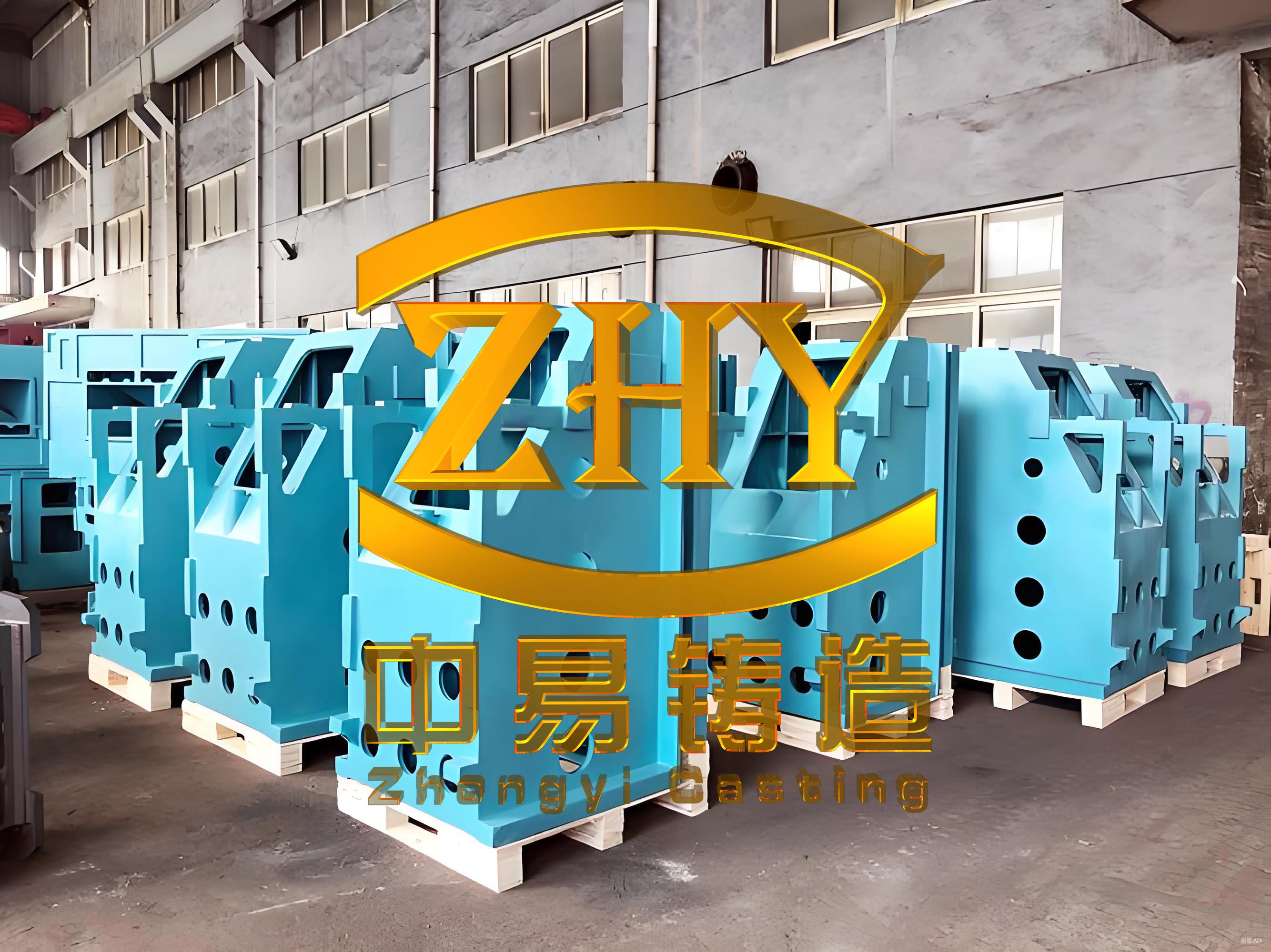
In my extensive experience in the foundry industry, I have encountered numerous challenges related to the deformation of large-scale machine tool castings. As the demand for heavy and ultra-heavy machine tools has grown, the production of massive castings, such as beams, beds, and tables exceeding 20 meters in length and weighing over 100 tons, has become common. These machine tool castings are critical components, and their dimensional stability is paramount. Even when a machine tool casting is free from defects like shrinkage or porosity, excessive deformation can render it unusable if the distortion exceeds the machining allowance. This article delves into the key factors influencing deformation in machine tool castings, drawing from my firsthand observations and analyses. I will explore how casting structure, chemical composition, cooling rates, holding times, and placement methods during pouring contribute to deformation quanta. Throughout this discussion, I will incorporate tables and mathematical models to summarize relationships and provide practical insights for controlling deformation in machine tool castings.
The deformation of a machine tool casting primarily stems from non-uniform solidification and cooling, leading to differential shrinkage across the casting. This is especially pronounced in large machine tool castings where thermal gradients are significant. Understanding and mitigating these effects is crucial for reducing scrap rates and ensuring the production of high-quality machine tool castings. In the following sections, I will analyze each factor in detail, supported by data and theoretical explanations.
Influence of Casting Structure on Deformation
From my perspective, the structure of a machine tool casting is the most dominant factor affecting its deformation. Components like beams, beds, and worktables often have varying wall thicknesses and complex geometries, which create uneven cooling conditions. For instance, thick sections like guide rails cool slower than thin walls, resulting in internal stresses that cause bending or twisting. In my work, I have observed that machine tool castings shorter than 5 meters exhibit negligible deformation, easily compensated by machining allowances. However, for longer machine tool castings, structural analysis becomes essential to predict deformation.
Generally, plate-like machine tool castings deform more than box-structured ones due to their lower rigidity. The length, width, and height ratios, along with the distribution of ribs, play a critical role. I often use empirical relationships to estimate deformation. For example, deformation tends to increase quadratically with length, as shown in the formula: $$ \delta = k L^2 $$ where $\delta$ is the deformation quanta (in mm), $L$ is the length of the machine tool casting (in m), and $k$ is a coefficient dependent on material and cross-section. For machine tool castings, $k$ typically ranges from 0.1 to 0.3 mm/m² based on my records.
To illustrate, I have compiled data from various machine tool castings I have handled, summarizing how deformation varies with length and structure:
| Casting Type | Length (m) | Width (m) | Height (m) | Average Deformation (mm/m) | Total Deformation (mm) |
|---|---|---|---|---|---|
| Beam (Box Structure) | 5-6 | 1.5-2 | 1-1.5 | 1.0-1.2 | 5-7.2 |
| Bed (Plate-like) | 7-8 | 2-2.5 | 0.8-1.2 | 1.5-1.8 | 10.5-14.4 |
| Worktable (Mixed) | 8-10 | 2.5-3 | 1-1.5 | ~2.0 | 16-20 |
| Long Beam (>10 m) | 10-20 | 2-3 | 1.5-2 | Requires secondary camber | 20-40+ |
For machine tool castings longer than 10 meters, I often apply a secondary camber during pattern design to counteract the parabolic deformation profile. The deformation is not linear; it increases towards the ends. In contrast, columnar machine tool castings, with high height-to-width ratios, rarely deform due to their symmetrical stress distribution. Similarly, box-structured machine tool castings with uniform walls exhibit minimal deformation, as shrinkage is more homogeneous.
Wall thickness disparities are another critical aspect. If a machine tool casting has sections differing significantly in thickness—say, a thick guide rail adjacent to a thin panel—the differential contraction can cause severe bending. In such cases, I modify the casting process by adding chills or optimizing risers to balance cooling, but often, the only solution is to incorporate a反变形量 (anti-deformation) in the pattern. For example, in a beam machine tool casting with a length of 12 meters and a thickness variation of 50 mm to 200 mm, the deformation can exceed 25 mm without compensatory measures.
Impact of Chemical Composition on Deformation
The chemical composition of the iron alloy fundamentally influences the deformation behavior of machine tool castings. In my experience, different grades of cast iron—gray iron and ductile iron—exhibit distinct deformation characteristics due to their microstructures and solidification modes.
Gray iron machine tool castings contain flake graphite, which acts as stress concentrators and weakens the matrix. Low-grade gray irons with high carbon equivalent (CE) have predominantly ferritic matrices and coarse graphite, resulting in lower tensile strength and hardness. These machine tool castings are more prone to deformation because the material yields easily under thermal stresses. The solidification of gray iron is directional; thin sections solidify first and contract, while thick regions remain liquid, leading to uneven shrinkage and deformation. The deformation quanta can be modeled using the formula: $$ \delta_g = \alpha_g \cdot \Delta T \cdot L $$ where $\delta_g$ is deformation for gray iron, $\alpha_g$ is the thermal expansion coefficient (approximately $10.5 \times 10^{-6} /^\circ\text{C}$), $\Delta T$ is the temperature gradient, and $L$ is length.
In contrast, high-grade gray irons with lower CE have pearlitic matrices and fine graphite, offering better resistance to deformation. However, ductile iron machine tool castings, with spheroidal graphite, provide the highest deformation resistance due to their superior mechanical properties. Ductile iron solidifies in a mushy manner, where the entire casting solidifies simultaneously, creating mutual constraints that reduce deformation but increase residual stresses. I have verified this through comparative studies; for instance, a beam machine tool casting of 9,750 mm length in gray iron deformed 8-10 mm more than an identical one in ductile iron.
The following table compares deformation quanta for different iron grades in similar machine tool castings:
| Iron Grade | Typical Composition (wt%) | Microstructure | Solidification Mode | Deformation Quanta (mm/m) for 8m Casting |
|---|---|---|---|---|
| Low-Grade Gray Iron | C: 3.4-3.8, Si: 1.8-2.4 | Ferrite + Coarse Graphite | Directional | 1.8-2.2 |
| High-Grade Gray Iron | C: 3.0-3.4, Si: 1.5-2.0 | Pearlite + Fine Graphite | Directional | 1.4-1.7 |
| Ductile Iron | C: 3.5-3.9, Si: 2.0-2.8 | Pearlite + Spheroidal Graphite | Mushy | 1.0-1.3 |
From this, it is evident that selecting the appropriate material is vital for controlling deformation in machine tool castings. In practice, I recommend ductile iron for critical, long-span machine tool castings where deformation must be minimized, despite its higher cost.
Effects of Cooling Rate on Deformation
Cooling rate is another pivotal factor I have manipulated to manage deformation in machine tool castings. The rate at which a casting cools depends on the molding method—whether it is made in a flask or a pit mold—and this significantly affects thermal gradients and subsequent distortion.
In flask molding, the machine tool casting is surrounded by resin sand in both cope and drag, providing relatively uniform cooling from all surfaces. Although thicker sections like guide rails cool slower, the overall temperature distribution is more balanced, leading to moderate deformation. Conversely, in pit molding, the drag side has substantial sand depth with poor heat dissipation, while the cope side cools faster due to exposure to air. This asymmetry exacerbates deformation because the lower part retains heat longer, and the resin sand may degrade, reducing its restraint capability. I recall a specific case of a 6.7-meter bed machine tool casting where pit molding resulted in 7-8 mm more deformation than flask molding under identical conditions.
The cooling rate can be quantified using Fourier’s law of heat conduction. For a machine tool casting, the temperature distribution over time $t$ can be described by: $$ \frac{\partial T}{\partial t} = \alpha \nabla^2 T $$ where $T$ is temperature, $\alpha$ is thermal diffusivity, and $\nabla^2$ is the Laplacian operator. The deformation $\delta_c$ due to cooling rate differences can be approximated as: $$ \delta_c = \beta \int (\Delta T) \, dx $$ where $\beta$ is a material-dependent constant, and $\Delta T$ is the temperature difference across the casting.
To mitigate this, I often use chills or cooling fins in thick sections of machine tool castings to accelerate cooling and reduce thermal gradients. The table below summarizes the impact of molding methods on deformation for a typical machine tool casting:
| Molding Method | Cooling Condition | Heat Dissipation | Typical Deformation Increase (mm) for 6-7m Casting |
|---|---|---|---|
| Flask Molding | Uniform from all sides | Moderate | Base (0) |
| Pit Molding | Asymmetric (slow bottom cooling) | Poor at bottom | +7 to +8 |
In practice, for large machine tool castings, I prefer flask molding whenever feasible to ensure more predictable deformation behavior.
Role of Holding Time and Casting Placement
Holding time—the duration the machine tool casting remains in the mold after pouring—is an external factor I have found crucial in controlling deformation. Insufficient holding time can lead to catastrophic deformation during handling or storage due to the casting’s low hot strength.
When a machine tool casting is lifted or supported improperly before it fully cools, gravity induces additional distortion. For example, if a long beam machine tool casting is lifted from its ends, the sagging effect amplifies any existing deformation. Conversely, supporting it from the sides or at intermediate points can help correct deformation by allowing uniform cooling and stress relief. The relationship between holding time $t_h$ and deformation $\delta_h$ can be expressed as: $$ \delta_h = \gamma \cdot (1 – e^{-t_h / \tau}) $$ where $\gamma$ is the maximum possible deformation due to handling, and $\tau$ is a time constant dependent on casting mass and geometry.
Moreover, the placement of the machine tool casting during pouring and cooling affects deformation. Orienting the casting to minimize thermal gradients—such as placing thick sections downward—can reduce distortion. I have documented cases where adjusting the placement reduced deformation by up to 15% in large machine tool castings. The following formula estimates the effect of placement on deformation: $$ \delta_p = \kappa \cdot \sin(\theta) \cdot L $$ where $\delta_p$ is placement-induced deformation, $\kappa$ is an orientation factor, and $\theta$ is the angle of inclination relative to horizontal.
To illustrate optimal practices, I have tabulated recommendations based on my experiences:
| Casting Length (m) | Minimum Holding Time (hours) | Recommended Support Method | Placement Orientation | Expected Deformation Reduction (%) |
|---|---|---|---|---|
| 5-8 | 24-48 | Side supports or multiple points | Horizontal with thick section down | 10-20 |
| 8-12 | 48-72 | Intermediate supports every 3-4 m | Slightly inclined (5-10°) | 20-30 |
| >12 | 72+ | Custom fixtures with continuous support | Optimized based on thermal analysis | 30-50 |
By adhering to these guidelines, I have successfully minimized scrappage due to deformation in machine tool castings.
Other Influencing Factors
Beyond the primary factors, I have noted that environmental conditions and chilling methods also affect deformation in machine tool castings. For instance, fluctuations in ambient temperature can alter cooling rates, while the use of chills in critical areas can control solidification. However, these are secondary compared to structure and material.
Conclusion
In summary, the deformation of machine tool castings is a complex phenomenon influenced by multiple interrelated factors. Based on my experience, the casting structure and material composition are the most significant and unchangeable elements driving deformation. For instance, long, plate-like machine tool castings in gray iron are inherently prone to higher distortion. However, through careful process design—such as selecting appropriate molding methods, optimizing holding times, and implementing strategic placement—I have effectively controlled deformation quanta. The integration of mathematical models and empirical data, as presented in this article, provides a foundation for predicting and mitigating deformation in machine tool castings. By prioritizing these measures, foundries can reduce rejection rates and enhance the quality of machine tool castings, ensuring they meet the stringent demands of modern heavy industry.