
In the production of large-scale, critical components for heavy machinery, such as the托盘 (tray) for coal pulverizing mills, achieving defect-free castings is paramount. These components are subjected to significant mechanical stress and require a combination of strength, ductility, and microstructural soundness. The material of choice for such applications is often ductile iron, specifically grade QT400-15, offering a good balance of properties. However, the intricate geometries of these parts, characterized by uneven wall thicknesses and thermal junctions, present significant challenges. A recurring issue in the manufacture of a large, ring-shaped托盘铸件 was the simultaneous appearance of subsurface porosity and internal shrinkage in casting at the ‘L’-shaped corner sections. This case study, from my firsthand engineering experience, details a comprehensive investigation into the root causes of these defects and the systematic corrective actions implemented to eliminate them.
Component Overview and Initial Manufacturing Process
The cast component in question is a large annular tray, acting as a structural support within a coal mill. Its key characteristics and initial production parameters are summarized below.
| Parameter | Specification / Value |
|---|---|
| Material | QT400-15 Ductile Iron |
| Mechanical Requirement (Single Test Block) | Tensile Strength ≥ 400 MPa, Elongation ≥ 15% |
| Mechanical Requirement (Attached Test Block) | Tensile Strength ≥ 370 MPa, Elongation ≥ 11% |
| Outer Diameter | ~3090 to 5000 mm |
| Height | 370 mm |
| As-Cast Weight | 5.19 t |
| Wall Thickness Profile | Min: 55 mm, Outer Ring: 80-100 mm with ‘L’-section junctions |
| Molding Process | Furan No-Bake Resin Sand |
| Gating System | Bottom-gating, semi-open type. Ratio: ΣSsprue : ΣSrunner : ΣSingate = 1.21 : 1.63 : 1 |
| Feeding | Multiple atmospheric vents (20×100/80×150 mm) placed on thick sections. |
| Chilling | Blind chills placed around the outer circumference of the core ring. |
The melting was conducted in a medium-frequency induction furnace with a charge blend of 60% steel scrap and 40% pig iron. The target chemical composition was tightly controlled, as shown in Table 2. Inoculation and spheroidization were performed using a sandwich method in the pouring ladle.
| Element | C | Si | Mn | P | S | Mg |
|---|---|---|---|---|---|---|
| Target Range | 3.50-3.80 | 2.2-2.7 | ≤0.40 | ≤0.05 | ≤0.020 | 0.03-0.06 |
Defect Manifestation and Root Cause Analysis
Post-casting and initial machining revealed two distinct yet potentially interrelated defect patterns, both localized to the problematic ‘L’-shaped corner.
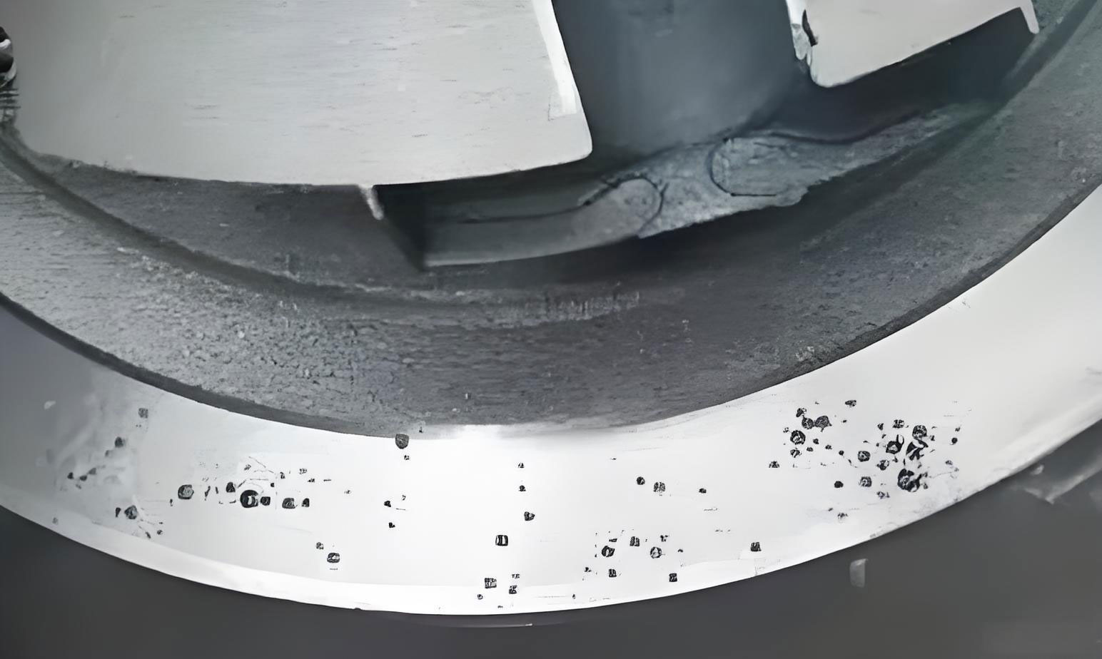
1. Analysis of Porosity Defects
The porosity appeared as a band of small, shiny, smooth-walled cavities just beneath the casting’s upper surface, following the contour of the annular corner. This is characteristic of reactive (subsurface) porosity. The mechanism typically involves a reaction at the metal-mold interface. In this case, the high heat from the molten iron (poured at 1350-1370°C) vaporizes residual moisture and organic compounds in the sand mold. The resulting steam can dissociate, and hydrogen can dissolve into the solidifying metal skin. As solubility drops during cooling, the hydrogen comes out of solution, forming pockets of gas trapped just below the surface.
The key contributing factors identified were:
- Excessive Mold/Gas Moisture: Inadequate drying or hardening of the large resin sand cores and molds can leave free moisture. The reaction is governed by: Fe + H2O → FeO + 2[H]. The atomic hydrogen [H] diffuses into the metal.
- Inadequate Mold Venting: While atmospheric vents were used, the sheer volume of gas generated from the large mold surface area may have overwhelmed the escape pathways, increasing back-pressure and forcing gas into the metal.
- Metal Composition: While within specification, the presence of trace elements like aluminum or higher residual magnesium/cerium can exacerbate the tendency for hydrogen pickup and pore formation.
2. Analysis of Shrinkage in Casting Defects
Upon machining the inner diameter, dispersed shrinkage in casting, or shrinkage porosity, was exposed within the thick ‘L’-section junction. This is a classic hot spot issue. Ductile iron solidifies through a mushy zone, and its volume change is a complex interplay of liquid contraction, austenite contraction, and graphite expansion. If the feeding is inadequate during the liquid/austenitic contraction phases, micro-voids form between dendrites, leading to scattered shrinkage in casting.
The fundamental shrinkage volume, \( V_{sh} \), can be expressed as a combination:
$$ V_{sh} = V_{liquid} + V_{austenitic} – V_{graphite} $$
Where \( V_{liquid} \) and \( V_{austenitic} \) are contraction volumes (positive), and \( V_{graphite} \) is the expansion volume (negative). The goal is to maximize \( V_{graphite} \) and ensure liquid feed metal compensates for the net positive shrinkage until the graphite expansion pressure is sealed within the casting.
The root causes for the observed shrinkage in casting were:
- Ineffective Chilling: The use of blind (embedded) chills against the core was ineffective. Their cooling power was likely insufficient to directionalize solidification and eliminate the thermal mass at the hot spot. They may have even created a localized “heat saturation” point.
- Inadequate Feeding: The small atmospheric vents acted more as gas vents than effective feeders. They likely solidified too quickly to provide meaningful liquid feed metal to compensate for the contraction in the massive hot spot.
- Sub-optimal Carbon Equivalent (CE): With a carbon content at the lower end of the range (~3.5%), the CE was lower, resulting in less graphite precipitation during eutectic solidification. This reduced the beneficial graphite expansion (\( V_{graphite} \)) that aids in “self-feeding” and counteracts shrinkage in casting.
| Defect Type | Primary Cause | Mechanism | Key Contributing Process Factors |
|---|---|---|---|
| Subsurface Porosity | Reactive Gassing | H2O(v) from mold → 2[H] in metal → H2(g) precipitation upon cooling. | High mold/core moisture, poor venting. |
| Shrinkage in Casting | Unfed Solidification Contraction | Liquid + Austenitic shrinkage > Graphite expansion at hot spot, forming interdendritic voids. | Ineffective chills, undersized feeders, low CE. |
Integrated Corrective Strategy and Implementation
The solution required a multi-pronged approach targeting both gas generation and solidification control simultaneously.
1. Measures to Eliminate Porosity
A. Reduction of Mold Gas Sources: A strict protocol was implemented to bake all large cores and significant sections of the mold cavity using mobile propane heaters. The target was to reduce the volatile content, particularly free moisture, in the sand immediately facing the metal to below 0.3 wt%. This directly reduced the quantity of steam generated by the reaction: $$ \text{Fe} + \text{H}_2\text{O} \xrightarrow{\text{>1350°C}} \text{FeO} + 2[\text{H}] $$.
B. Enhancement of Mold Exhaust Capacity: The original venting was augmented significantly:
- Permeability: Vent rods made of highly permeable material were strategically inserted into the core and the drag mold sections near the upper surface.
- Escape Pathways: The number and cross-sectional area of vent passages to the outside atmosphere were doubled. This ensured a lower gas back-pressure (\( P_{gas} \)) in the mold cavity, reducing the driving force for gas invasion. The condition for gas entry can be simplified as \( P_{gas} > P_{metal} + \sigma / r \), where \( P_{metal} \) is metallostatic pressure and \( \sigma / r \) is the capillary pressure at the pore radius. By keeping \( P_{gas} \) low, we prevent this inequality from being true.
2. Measures to Eliminate Shrinkage in Casting
A. Redesign of Cooling Strategy: The blind chills were completely removed. They were replaced with prominently placed external (live) chills on the drag side of the mold, directly facing the ‘L’-section’s thickest part. These massive steel chills provided intense, directional heat extraction, effectively creating a temperature gradient that promoted solidification away from the hot spot and towards the feeder. This transformed the solidification pattern from one favoring a dispersed mushy zone to a more directional one, reducing the vulnerable time for shrinkage in casting formation.
B. Optimization of Feeding System: The small atmospheric vents were replaced with significantly larger necked-down blind feeders (risers). Their dimensions were increased from 20×100/80×150 mm to 20×100/170×195 mm. This served two critical functions:
- Liquid Feeding: The larger thermal mass provided a prolonged reservoir of liquid iron to feed the substantial liquid and austenitic contraction (\( V_{liquid} + V_{austenitic} \)) of the hot spot.
- Pressure Feeding & Sealing: The feeder design ensured it solidified last. During the later stages of solidification, when graphite expansion (\( V_{graphite} \)) begins within the casting, the feeder neck would solidify shut, effectively “sealing” the casting and allowing the internal graphite expansion pressure to compensate for any remaining micro-shrinkage, thereby mitigating shrinkage in casting.
C. Adjustment of Metallurgical Composition: The target carbon content was raised towards the upper limit of the specification, aiming for approximately 3.75%. This increased the Carbon Equivalent (CE = %C + 0.33(%Si)), pushing the iron closer to the eutectic point. The benefits are quantified in the solidification model:
$$ V_{net} = \epsilon_l \cdot f_l + \epsilon_{au} \cdot f_{au} – \epsilon_{gr} \cdot f_{gr} $$
Where \( \epsilon \) represents the volumetric change coefficient and \( f \) the fraction for liquid (l), austenitic (au), and graphite (gr) phases. Increasing carbon significantly increases the graphite fraction \( f_{gr} \), thereby maximizing the expansive term \( \epsilon_{gr} \cdot f_{gr} \). This enhanced “self-feeding” or “autogenous feeding” effect is crucial for preventing shrinkage in casting in ductile iron. This was done while carefully monitoring for graphite flotation by controlling pouring temperature and inoculation practice.
| Target Defect | Corrective Action | Mechanism / Principle |
|---|---|---|
| Porosity | Core/Mold Baking | Reduces reactant H2O in mold sand: ↓(Fe + H2O → FeO + 2[H]) |
| Enhanced Venting | Lowers mold gas pressure \( P_{gas} \), preventing \( P_{gas} > P_{metal} + \sigma/r \). | |
| Shrinkage in Casting | Replace Blind with Live Chills | Creates steep thermal gradient, directional solidification, eliminates hot spot. |
| Enlarge Feeders | Provides liquid feed for \( V_{liquid}+V_{austenitic} \); seals to utilize \( V_{graphite} \). | |
| Increase Carbon Content | Increases CE → increases \( f_{gr} \) → maximizes expansive \( \epsilon_{gr} \cdot f_{gr} \) term. |
Results and Validation
The implementation of this integrated corrective strategy proved entirely successful. In the subsequent production of over 28 castings of the same or geometrically similar托盘 designs, neither subsurface porosity nor internal shrinkage in casting defects were observed. The castings met all dimensional and surface quality requirements.
Furthermore, mechanical property testing from attached test blocks confirmed that the process changes did not compromise the material specifications. The properties were consistent and excellent, as demonstrated in the statistical summary below.
| Property | Average Value | Standard Deviation | Specification (Attached Block) | Met? |
|---|---|---|---|---|
| Tensile Strength (MPa) | 434.2 | 16.5 | ≥ 370 MPa | Yes |
| Elongation (%) | 15.2 | 1.4 | ≥ 11% | Yes |
| Hardness (HBW) | 147 | 3.8 | – | – |
Metallographic examination consistently showed a spheroidal graphite structure of grade 2 (excellent) with a nodule size of 7 (fine), and a ferrite content exceeding 95%, which is ideal for the required ductility.
Conclusion and General Principles
This case study underscores that defects in large, complex ductile iron castings are seldom due to a single cause. The co-occurrence of porosity and shrinkage in casting often points to systemic issues in the molding and solidification control processes. The successful resolution hinged on a disciplined, two-pronged analysis:
1. For Gas-Related Defects: The focus must be on minimizing gas generation at the source (mold dryness) and ensuring its unimpeded evacuation from the mold cavity (venting efficiency). Controlling the reaction kinetics at the metal-mold interface is critical.
2. For Shrinkage in Casting Defects: The strategy must holistically manage solidification. This involves:
- Thermal Gradient Management: Using effective chills to control the solidification sequence and eliminate isolated hot spots.
- Feeding System Design: Designing feeders that are adequate in volume and timing to provide liquid feeding during the contraction phases and subsequently seal to harness the graphite expansion pressure.
- Metallurgical Optimization: Leveraging the unique properties of ductile iron by employing a high carbon equivalent (high hypoeutectic or slightly hypereutectic composition) to maximize the beneficial graphite expansion that counteracts shrinkage in casting.
The relationship between process parameters and soundness can be conceptualized by an overall quality function \( Q \), where avoiding shrinkage in casting is a key output:
$$ Q \propto \frac{G \cdot (V_{graphite} + V_{feeder})}{P_{gas} \cdot t_{mushy}} $$
Here, \( G \) is the temperature gradient (enhanced by chills), \( V_{graphite} \) is the graphite expansion volume (enhanced by high CE), \( V_{feeder} \) is the effective feeding volume, \( P_{gas} \) is the mold gas pressure (reduced by drying and venting), and \( t_{mushy} \) is the mushy zone solidification time (reduced by chills and high CE). By systematically addressing each factor in this equation—reducing the denominator and increasing the numerator—the production of sound, heavy-section ductile iron castings free from both porosity and shrinkage in casting becomes a reliable and repeatable outcome.