
In my extensive experience with heavy machinery casting, I have encountered numerous challenges related to defect formation, particularly in large-scale components. One prominent case involves the production of QT400-15 tray castings used in coal mill systems. These trays are critical functional parts that must withstand high torsional, impact, and vibrational loads, necessitating superior strength, toughness, and ductility. The inherent design, featuring a continuous circular “L”-shaped corner, leads to uneven wall thickness and poor venting, making the casting highly susceptible to gas holes and shrinkage in casting. These defects, if severe, can result in scrapping of the entire component, causing significant economic loss and production delays. This article delves into a first-hand analysis of the root causes and presents comprehensive measures to eliminate these issues, ensuring the reliable quality of tray castings.
The tray casting is a large circular disc with varying outer diameters ranging from 3,090 mm to 5,000 mm, a height of 370 mm, and a rough weight between 5.1 to 9 tons. The wall thickness varies, with a minimum of 55 mm and peripheral walls of 80–100 mm. The problematic area is the abrupt “L”-shaped corner, which acts as a thermal junction, promoting localized heat accumulation. The technical specifications require a tensile strength ≥ 400 MPa and elongation ≥ 15% for separately cast test blocks, and ≥ 370 MPa tensile strength with ≥ 11% elongation for attached test blocks. Below is a summary of the casting’s key parameters:
| Parameter | Specification |
|---|---|
| Outer Diameter Range | 3,090 – 5,000 mm |
| Height | 370 mm |
| Rough Weight | 5.1 – 9 tons |
| Minimum Wall Thickness | 55 mm |
| Peripheral Wall Thickness | 80 – 100 mm |
| Key Defect Location | “L”-shaped corner (thermal junction) |
| Material Grade | QT400-15 (Ductile Iron) |
| Tensile Strength (Attached Test) | ≥ 370 MPa |
| Elongation (Attached Test) | ≥ 11% |
The original casting process utilized furan resin sand molding, with the largest diameter face as the parting plane. The mold consisted of an outer contour formed by the flask and an inner contour by cores, including a ring-shaped core and a cylindrical core. A bottom-gating system with a semi-closed design was employed to control pouring speed and slag trapping. The gating ratio was set at ΣSsprue : ΣSrunner : ΣSingate = 1.21 : 1.63 : 1. To leverage the graphitization expansion of ductile iron, open risers with dimensions 20 mm × 50 mm at the bottom and 80 mm × 150 mm at the top were placed in thick sections. Additionally, dark chills were positioned around the ring core to aid cooling and enhance densification. Attached test blocks of size 180 mm × 70 mm × 70 mm were used for quality verification.
Melting was conducted in a 20-ton medium-frequency induction furnace, with a charge composition of 60% scrap steel and 40% pig iron. The target chemical composition range is summarized in the table below:
| Element | Control Range (wt.%) |
|---|---|
| Carbon (C) | 3.50 – 3.80 |
| Silicon (Si) | 2.2 – 2.7 |
| Manganese (Mn) | ≤ 0.4 |
| Phosphorus (P) | ≤ 0.05 |
| Sulfur (S) | ≤ 0.020 |
| Magnesium (Mg) | 0.03 – 0.06 |
The superheating temperature was maintained at 1,500–1,520°C, with a spheroidizing temperature of 1,450–1,480°C and a pouring temperature of 1,350–1,370°C. Post-pouring cooling lasted 60 hours before shakeout. Spheroidization was performed using the sandwich method with 1.1–1.3% nodularizer, while inoculation combined barium-silicon and ferrosilicon alloys, totaling 0.8–1.2%.
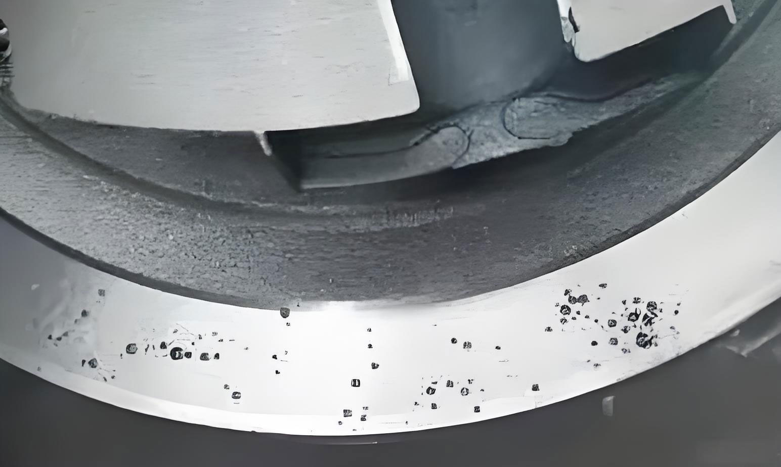
Despite these measures, the produced tray castings exhibited defects: gas holes on the outer circumferential surface and shrinkage in casting at the inner ring after machining. The gas holes appeared as smooth-walled cavities near the surface, characteristic of invasive gas entrapment. The shrinkage in casting manifested as dispersed porosity in the thick “L”-shaped corner regions, indicating inadequate feeding during solidification. The presence of these defects underscores the complexity of managing shrinkage in casting in large ductile iron components.
To systematically address these issues, I analyzed the formation mechanisms. Gas holes in castings are typically classified into three types: precipitated, reactive, and invasive. In this case, the smooth walls and subsurface location pointed to invasive gas holes. These form when gases generated from the mold or core under high-temperature metal penetration exceed the external resistance pressure and invade the liquid metal, leading to bubble formation that becomes trapped. Measurement revealed that the moisture content in the sand molds and cores ranged from 0.5% to 0.6%, exceeding the required ≤0.3%. This excessive moisture, coupled with limited venting, directly contributed to gas hole generation. The gas pressure at the metal-mold interface can be modeled using the ideal gas law applied to evolving gases:
$$ P_g = \frac{n_g R T}{V} $$
where \( P_g \) is the gas pressure, \( n_g \) is the moles of gas generated from moisture vaporization and resin decomposition, \( R \) is the gas constant, \( T \) is the interfacial temperature, and \( V \) is the volume of the gap. When \( P_g \) surpasses the sum of metallostatic pressure and atmospheric resistance, invasion occurs, leading to defects.
Regarding shrinkage in casting, it is essentially a form of shrinkage porosity resulting from inadequate compensation for liquid and solidification contraction. Ductile iron, with its wide freezing range, is prone to dispersed shrinkage in casting due to the sum of liquid and solidification shrinkage exceeding solid-state shrinkage. The “L”-shaped corner acts as a thermal junction, where heat accumulation delays solidification, creating a vulnerable zone for shrinkage in casting. The volume change during solidification can be expressed as:
$$ \Delta V = V_l \cdot \alpha_l + V_s \cdot \beta_s $$
where \( \Delta V \) is the total volumetric shrinkage, \( V_l \) is the volume of liquid metal, \( \alpha_l \) is the liquid contraction coefficient, \( V_s \) is the volume solidified, and \( \beta_s \) is the solidification shrinkage coefficient. For ductile iron, \( \beta_s \) is significant due to graphite precipitation, but improper cooling can lead to negative pressure zones causing shrinkage in casting. The thermal gradient \( \nabla T \) at the junction is critical, and if insufficient, it hinders directional solidification toward feeders.
To mitigate gas holes, I focused on reducing mold moisture and enhancing permeability. First, I implemented baking of sand cores and molds to lower moisture content below 0.3%. For large cores unable to fit in drying ovens, in-situ baking within the mold cavity was adopted. Second, I improved venting by incorporating vent ropes in cores and molds to facilitate gas escape, reducing the likelihood of invasive gas. These steps directly target the gas generation and transport mechanisms, ensuring that \( P_g \) remains below the invasion threshold.
For shrinkage in casting, the strategy involved transforming dispersed shrinkage into concentrated shrinkage that could be diverted to risers, while maximizing graphitization expansion for self-feeding. I initiated three key modifications. First, I replaced the dark chills with open chills, repositioning them to better cover the “L”-shaped corner. This enhanced cooling capacity, eliminated the thermal junction, and promoted more uniform solidification. The chill design now provided a higher heat extraction rate \( Q \), given by:
$$ Q = k \cdot A \cdot \nabla T $$
where \( k \) is the thermal conductivity of the chill material, \( A \) is the contact area, and \( \nabla T \) is the temperature gradient. Second, I increased the size of open risers from 20×50/80×150 to 20×100/170×195, enlarging the liquid reservoir for better feeding. The riser efficiency \( \eta_r \) relates to its modulus \( M_r \):
$$ \eta_r = \frac{V_f}{V_r} \propto M_r^{3/2} $$
where \( V_f \) is the feed volume and \( V_r \) is the riser volume. A larger \( M_r \) improves feeding to combat shrinkage in casting. Third, I adjusted the melt chemistry, raising the carbon content to around 3.75% within a carbon equivalent (CE) range of 4.3–4.5%, approaching the eutectic point. Higher carbon promotes graphite precipitation, enhancing graphitization expansion pressure \( P_{gr} \), which counteracts shrinkage in casting. The expansion pressure can be approximated as:
$$ P_{gr} = \frac{E_{gr} \cdot \Delta V_{gr}}{V_c} $$
where \( E_{gr} \) is the elastic modulus of the expanding graphite, \( \Delta V_{gr} \) is the volume increase from graphite formation, and \( V_c \) is the casting volume. This self-feeding effect is crucial for reducing shrinkage in casting.
The table below contrasts the original and optimized process parameters for addressing shrinkage in casting:
| Aspect | Original Process | Optimized Process |
|---|---|---|
| Mold Moisture Content | 0.5–0.6% | ≤0.3% (via baking) |
| Venting System | Standard vents | Added vent ropes in cores/molds |
| Chill Type and Placement | Dark chills around ring core | Open chills at “L”-shaped corner |
| Riser Dimensions | 20×50/80×150 | 20×100/170×195 |
| Carbon Content (wt.%) | 3.50–3.80 | ~3.75 (CE 4.3–4.5%) |
| Cooling Strategy | Generalized chilling | Targeted chilling for thermal junction |
| Solidification Control | Moderate gradient | Enhanced gradient to prevent shrinkage in casting |
After implementing these measures, I produced multiple tray castings of the same specification. None exhibited gas holes or shrinkage in casting defects. The attached test blocks showed tensile strengths of 409–464 MPa and elongations of 13–17%, meeting the required standards. Metallographic analysis confirmed a spheroidization grade of 2 and graphite size of 7, indicating high-quality ductile iron. The successful elimination of shrinkage in casting validates the effectiveness of the integrated approach.
In conclusion, addressing shrinkage in casting in large QT400-15 tray components requires a holistic strategy. By reducing mold moisture and enhancing venting, invasive gas holes can be prevented. For shrinkage in casting, optimizing chill design to eliminate thermal junctions, enlarging risers for liquid feeding, and adjusting carbon content to leverage graphitization expansion are pivotal. These measures, derived from hands-on analysis, not only resolve defects but also ensure reproducible quality for large, complex ductile iron castings. The continuous battle against shrinkage in casting demands attention to both process parameters and material science, underscoring the importance of adaptive engineering in foundry operations.