
The persistent challenge of shrinkage in casting production, particularly in complex, thin-walled components like exhaust manifolds, represents a significant hurdle to achieving both quality and cost-effectiveness. As a foundry engineer, I recently led a project to diagnose and eliminate a severe shrinkage in casting issue that was plaguing the production of a silicon-molybdenum (SiMo) ductile iron four-cylinder exhaust manifold. The initial scrap rate due to shrinkage porosity was an unsustainable 40%, primarily located at the critical flange areas. Through a systematic investigation and a series of targeted improvements, we successfully reduced the defect rate to below 2% while simultaneously increasing the casting yield by 5%. This article details the diagnostic process, the root causes identified, and the effective solutions implemented, underscoring the intricate interplay between metallurgy and gating/risering design in combating shrinkage in casting defects.
1. The Problem: Chronic Shrinkage in a Critical Component
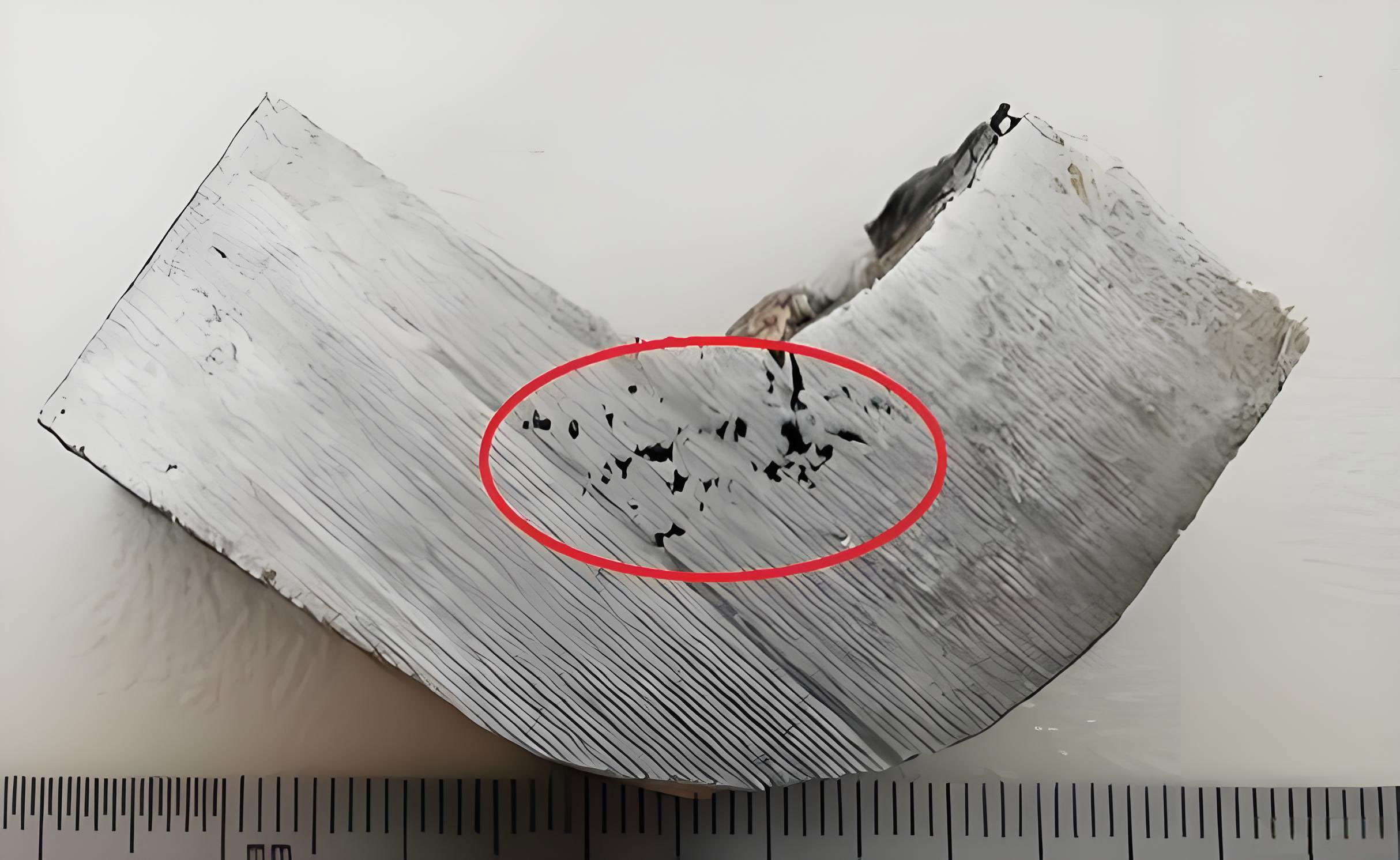
The component in question is a four-cylinder exhaust manifold cast in GJS-SiMo51 (SiMo ductile iron). Its geometry is inherently challenging for soundness: thin-walled tubes (~5.5 mm) connect to thicker sections like the intake flanges (18 mm) and various mounting bosses (25 mm diameter). These thicker sections act as isolated thermal nodes, creating natural hotspots prone to shrinkage in casting during solidification. The original manufacturing process utilized green sand molding on a jolt-squeeze line, with four castings arranged in a mold. Each casting was fed by three risers: two for the intake flange and one as an overflow/feed riser at the exhaust flange. Despite this risering, radiographic and cut-up inspections revealed severe shrinkage porosity, often accompanied by minor gas entrapment, extending from the riser neck deep into the flange body, leading to rejection.
2. Initial Analysis and Root Cause Hypothesis
The presence of shrinkage, sometimes mixed with minor gas, pointed toward a multifactorial origin. We hypothesized that the root causes of this pervasive shrinkage in casting could be categorized into two main areas:
A. Metallurgical Factors: The propensity for shrinkage in casting of ductile iron is highly sensitive to chemistry and melt treatment.
– Carbon Equivalent (CE): A low CE reduces the graphite expansion phase during eutectic solidification, diminishing its self-feeding capability and increasing the demand for external feed metal from risers.
– Residual Magnesium: While essential for nodularization, excessive residual Mg increases shrinkage tendency by promoting a carbidic, pasty solidification mode.
– Melt Cleanliness: Inclusions can impede the flow of feed metal during the final stages of solidification, exacerbating shrinkage in casting.
B. Process & Design Factors: The geometry and feeding system design are paramount.
– Riser Efficacy: The riser must remain molten longer than the casting section it is intended to feed. Its size, expressed by its modulus (volume/surface area ratio), must be correctly calculated.
– Riser Placement and Contact: A riser placed too close to a casting hotspot can create a “contact hot spot,” effectively enlarging the thermal mass that needs feeding and delaying the freezing of the riser neck.
– Riser Neck Design: The neck must be designed to allow feed metal flow during solidification but also freeze promptly after feeding is complete to prevent shrinkage in casting from backing up into the casting itself.
The original process parameters and riser design are summarized below:
| Parameter | Original Specification |
|---|---|
| Casting Weight (per piece) | 6.75 kg |
| Mold Weight (4 pieces) | 64 kg |
| Casting Yield | 42.2% |
| Risers per Casting | 3 |
| Riser Dimension (Top Dia. x Height) | φ54.3 mm x 120 mm |
| Riser Modulus (MR) | ~1.31 cm |
| Distance from Riser to Flange | 7 mm |
3. The Improvement Journey: A Two-Phase Approach
3.1 Phase One: Metallurgical Optimization
Our first intervention focused on stabilizing and optimizing the melt chemistry and processing to reduce the inherent shrinkage in casting tendency. The goal was to promote a more favorable solidification pattern with robust graphite expansion. We implemented strict controls:
- Charge Materials: Use of clean steel scrap, high-quality pig iron, and limiting returns to <30%.
- Melting Practice: Controlled charge sequence, superheating temperature, and holding time to improve homogeneity and reduce inclusions.
- Chemistry Control: Tightening the ranges for key elements using optical emission spectrometry. We aimed for a higher, more consistent Carbon Equivalent (CE). The target was calculated as: $$CE = \%C + \frac{\%Si + \%P}{3}$$ Targeting approximately 4.7–4.75%.
- Inoculation & Treatment: Precise addition of 1.0–1.05% Mg6RE2 nodularizer and 75SiFe inoculant to control nodule count and shape, and to keep residual Mg in the optimal 0.035–0.045% range.
- Pouring Practice: High tap temperature (1560 ±10 °C) and faster pour times (<8 min for the ladle) to minimize temperature loss and thermal gradient issues between first and last molds in a pour.
The resulting chemical composition before and after treatment is shown below:
| Element | Target (Post-Treatment) | Typical Achieved Range |
|---|---|---|
| Carbon (C) | 3.35 – 3.45% | 3.38 – 3.42% |
| Silicon (Si) | 4.0 – 4.2% | 4.05 – 4.15% |
| Manganese (Mn) | ≤ 0.30% | 0.25 – 0.28% |
| Molybdenum (Mo) | 0.80 – 0.90% | 0.84 – 0.87% |
| Residual Magnesium (Mg) | 0.038 – 0.045% | 0.040 – 0.043% |
| Carbon Equivalent (CE) | 4.70 – 4.78% | 4.72 – 4.76% |
Result: This phase yielded a noticeable improvement. Scrap due to shrinkage in casting dropped from 40% to ~26.6%. However, this level was still commercially unacceptable. It proved that while good metallurgical control is a necessary foundation, it alone was insufficient to solve the problem. The primary issue likely resided in the casting process design itself.
3.2 Phase Two: Redesign of the Feeding System
Analysis of the defect location—always at the riser neck—and the original design pointed to a critical flaw: the risers were both too large and placed too close to the flange. This created a massive “contact hot spot,” where the thermal mass of the riser base and the flange acted as a single, large slow-cooling zone. The large riser (modulus 1.31 cm) provided ample feed metal but also delivered excessive heat, delaying solidification of the riser neck. Consequently, the neck remained open too long, allowing shrinkage in casting to propagate from the riser back into the solidifying flange.
The governing principle for riser design is that the riser must solidify after the casting section it feeds. This is ensured by having a higher riser modulus (MR) than the casting modulus (MC). The modulus is calculated as: $$M = \frac{V}{A}$$ where \(V\) is volume and \(A\) is the cooling surface area. For a cylindrical riser, neglecting the top contact area, the modulus approximates to \( \frac{Diameter}{4} \) or \( \frac{Height}{4} \), whichever is smaller. Our redesign focused on two key parameters:
- Increase Riser-to-Casting Distance: To break the contact hot spot, we increased the gap between the riser and the flange from 7 mm to 14 mm. This allowed the thin section between them to solidify and isolate the thermal masses earlier, promoting directional solidification toward the riser.
- Optimize Riser Size (Modulus): We recalculated the required feed metal volume based on the solidification shrinkage of ductile iron (≈3-4%) and the modulus of the flange hot spot. The goal was to use the smallest effective riser. We reduced the riser dimensions to a top diameter of φ55 mm and a height of 85 mm (75 mm above the parting line). This gave a new riser modulus: $$M_{R(new)} \approx \frac{55 mm}{4} = 13.75 mm = 1.375 cm \text{ (based on diameter)}$$ $$ \text{Or } M_{R(new)} \approx \frac{85 mm}{4} = 21.25 mm = 2.125 cm \text{ (based on height)}$$ The controlling modulus is the smaller one, ~1.38 cm. This was still significantly larger than the flange modulus (~0.9 cm), ensuring it would solidify last, but its reduced volume (≈1.38 kg vs. 2.6 kg) drastically lowered its heat input.
The comparison between the old and new riser design is critical to understanding the solution for shrinkage in casting:
| Design Feature | Original Design | Optimized Design | Impact on Shrinkage |
|---|---|---|---|
| Riser Modulus (MR) | ~1.31 cm | ~1.38 cm | Maintained feeding capacity. |
| Riser Volume/Weight | ~2.6 kg | ~1.38 kg | Reduced heat input, minimized contact hot spot. |
| Distance to Casting | 7 mm | 14 mm | Eliminated severe contact hot spot, allowed neck to freeze promptly. |
| Riser Neck | Effectively part of the hot spot | Became a defined, coolable channel | Prevented shrinkage from backing up into casting. |
| Total Mold Weight | 64 kg | 58.4 kg | Increased yield. |
4. Results and Validation
The implementation of the combined metallurgical and design changes yielded transformative results. A validation run of 60 castings produced only one with minor neck shrinkage—a defect rate of 1.6%. More importantly, this result was sustained in mass production over thousands of castings, with the scrap rate for shrinkage in casting consistently maintained below 2%. Furthermore, the reduction in riser metal increased the casting yield from 42.2% to 46.2%, a direct 5% gain in efficiency and cost savings.
The success of this project can be distilled into a simple, actionable formula for preventing shrinkage in casting in similar ductile iron applications:
$$ \text{Sound Casting} = \text{Controlled Metallurgy} + \text{Precise Feeding Design} $$
Where Controlled Metallurgy emphasizes High CE, Optimal Residual Mg, and Clean Melting. And Precise Feeding Design emphasizes Adequate but Minimal Riser Modulus (MR > MC), Strategic Riser Placement to avoid contact hot spots, and a Riser Neck designed for timely closure.
5. Conclusion and Learned Principles
Solving the severe shrinkage in casting problem in the SiMo exhaust manifold was a powerful lesson in holistic foundry engineering. The key takeaway is that riser design is a exercise in precision, not just generosity. A larger riser is not universally better. An oversized riser can be as detrimental as an undersized one due to the excessive heat it introduces, which can disrupt the intended solidification gradient and keep critical pathways like the riser neck open for too long, directly causing shrinkage in casting.
The process confirmed that:
1. Metallurgical Control is the Foundation: Stabilizing chemistry (especially CE and Mg) and melt quality reduces the inherent shrinkage tendency, making the casting more responsive to proper feeding.
2. Feeding System Geometry is Decisive: The size, location, and neck design of risers must be carefully calculated based on the modulus of the casting sections. Breaking contact hot spots by increasing the riser-casting gap can be a simple yet highly effective remedy.
3. Systematic Diagnosis is Key: Isolating variables—first metallurgy, then design—allowed us to identify the true root cause. The initial improvement from metallurgy alone signaled we were on the right path, but the dramatic final improvement from the riser redesign pinpointed the core issue.
This case study stands as a testament to the fact that overcoming shrinkage in casting defects requires a balanced, scientific approach that harmonizes the art of metallurgy with the principles of solidification science.