
The persistent challenge of shrinkage defects, particularly at the riser neck junction, in heavy-section ductile iron (DI) castings such as engine blocks or crankcases represents a significant hurdle in achieving high yields and consistent quality. The economic impact of scrapping a multi-ton component after extensive machining is substantial. Through years of hands-on process development and troubleshooting, I have come to understand that resolving shrinkage in casting is not merely about adding more feed metal; it is a delicate balancing act involving solidification control, thermal management, and a profound understanding of the unique metallurgy of ductile iron. This article consolidates my experience and methodology, employing analytical tools like tables and formulas, to provide a comprehensive framework for addressing this critical defect.
1. The Unique Solidification Behavior of Ductile Iron
To effectively combat shrinkage in casting, one must first abandon the simplistic “liquid-to-solid shrinkage” model applicable to white irons or steels. Ductile iron solidifies through a mushy, pasty mode with a wide freezing range. The key phenomena governing its soundness are graphite expansion and the formation of an austenitic shell.
Upon inoculation, graphite precipitates as spheroidal nodules. As the temperature drops into the eutectic range, these nodules become enveloped by shells of austenite (γ-Fe). The subsequent growth of the graphite nodule occurs primarily by diffusion of carbon atoms through this austenite shell, not from direct contact with the surrounding liquid. This process can be conceptually described by a simplified diffusion-controlled growth equation:
$$ r(t) = \alpha \sqrt{D_c \cdot t} $$
Where \( r(t) \) is the radius of the graphite nodule at time \( t \), \( D_c \) is the diffusion coefficient of carbon in austenite, and \( \alpha \) is a constant dependent on supersaturation. The expansion associated with graphite formation (graphite has a lower density than liquid iron) generates internal pressure within the eutectic cell (a unit of graphite+austenite).
The final soundness of the casting depends on the timing and magnitude of this expansion relative to the thermal contraction of the austenitic skeleton. If the expanding eutectic cells can remain interconnected until the late stages of solidification, the expansion can compensate for the contraction, leading to “self-feeding.” However, if the austenite dendrites or shells form a rigid network early, isolating liquid pockets, the internal expansion pressure can actually push the cells apart, creating intercellular micro-porosity – the very essence of shrinkage in casting in ductile iron. This is often termed “expansion porosity.” The transition from feeding to porosity creation is schematically represented in the following states:
| Stage | Structural State | Pressure State | Potential for Shrinkage |
|---|---|---|---|
| Early Solidification | Liquid with isolated eutectic cells. Austenite dendrites forming. | Low internal pressure. Liquid can flow. | Low. |
| Mid Solidification | Eutectic cells growing, impinging. Interconnected liquid channels exist. | High expansion pressure. Pressure transmitted through liquid channels. | Controlled by pressure and channel availability. |
| Late Solidification | Rigid austenite network. Liquid pockets isolated. | High localized pressure with no escape path. | VERY HIGH. Expansion forces create voids between cells. |
The riser’s role in this system is critical but nuanced. A riser must provide liquid feed metal during the initial liquid contraction phase before significant graphite expansion begins. Crucially, the riser neck must freeze at the right moment: late enough to allow this initial feed, but early enough to isolate the casting from the riser before the intense graphite expansion phase in the riser itself begins. If the neck stays open too long, the high expansion pressure from the still-liquid riser can force residual liquid back into the already-pasty casting region, disrupting the delicate semi-solid structure and exacerbating shrinkage in casting at the neck junction. This is a common root cause of the problem.
2. Case Analysis: The Engine Block Challenge
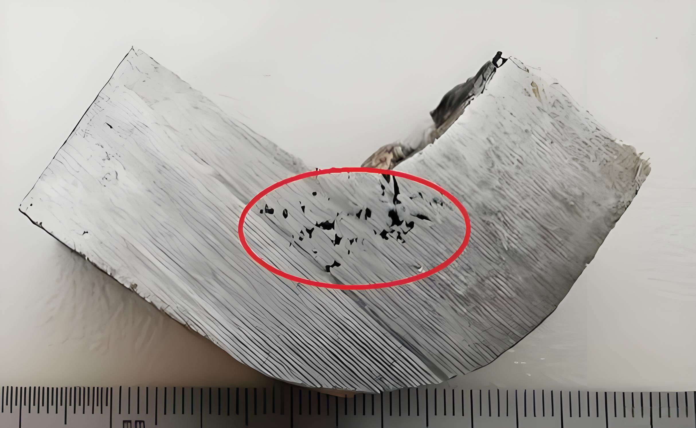
Consider a representative scenario: a complex DI engine block (Grade QT400-15) with varying wall thickness (10mm to 98mm), weighing several tons. The initial process employed side risers on thick sections like the bearing bulkheads and deck faces. Despite using insulated risers, ultrasonic testing consistently revealed subsurface shrinkage in casting clusters at the riser roots after machining.
Initial Hypothesis & Failed Remedy: The immediate assumption was inadequate riser volume. The riser diameter was increased by 25%. The result? The shrinkage in casting defect persisted virtually unchanged. This was the first critical clue: the problem was not primarily about the total feed metal volume.
Root Cause Investigation: A data-driven analysis was conducted. We compiled process data from both sound and defective castings. Two parameters showed a clear correlation:
| Parameter | Range in Sound Castings | Range in Defective Castings | Observation |
|---|---|---|---|
| Carbon Equivalent (CE) | 4.43 – 4.62% | 4.43 – 4.54% | No significant correlation. |
| Pouring Temperature | 1360°C – 1371°C | 1373°C – 1378°C | Strong correlation. Defects associated with higher pouring temperatures. |
| Riser Neck Geometry | Not Applicable (Original) | φ60 mm cylindrical neck | Neck created a significant isolated thermal mass. |
Thermal Analysis & Modulus Calculation: The riser neck was analyzed as a separate thermal node. The modulus \( M \), a measure of a section’s cooling rate, is given by \( M = \frac{V}{A} \), where \( V \) is volume and \( A \) is cooling surface area. For the original cylindrical neck (diameter \( d = 60 \) mm, length \( L \approx d \)):
$$ M_{neck-original} = \frac{\pi (d/2)^2 L}{2\pi (d/2)L + 2\pi (d/2)^2} = \frac{\pi (30^2) (60)}{2\pi(30)(60) + 2\pi(30)^2} \approx \frac{169560}{11304 + 5652} \approx 10.0 \text{ mm} $$
This modulus was comparable to or even greater than the modulus of the adjacent casting hot spot (the bearing bulkhead). Consequently, the neck itself became a secondary hot spot, solidifying later than intended. This delayed neck closure, allowing the riser to remain hydraulically connected during the casting’s graphite expansion phase. The resulting pressure interference disrupted the final solidification sequence at the junction, leading to shrinkage in casting.
3. The Integrated Solution Framework
The corrective strategy was multi-pronged, targeting the identified root causes: excessive thermal mass at the neck and overly high pouring temperature.
3.1. Riser Neck Redesign for Controlled Freezing
The goal was to design a neck that would freeze promptly after fulfilling its initial liquid feeding duty. This was achieved by changing from a cylindrical to a “choke” or “spearhead” geometry. The new neck had a rectangular cross-section (30mm x 60mm) and a reduced length (25mm), significantly increasing its cooling surface area to volume ratio.
Calculating the modulus for the new design:
$$ M_{neck-new} = \frac{V}{A} = \frac{(30 \times 60 \times 25)}{2[(30\times25) + (60\times25)] + (30\times60)} = \frac{45000}{2[750 + 1500] + 1800} = \frac{45000}{4500 + 1800} \approx 7.1 \text{ mm} $$
The modulus decreased from ~10.0 mm to ~7.1 mm, a 29% reduction. This ensured the neck would solidify before the main hot spot of the casting, effectively isolating it from the riser’s later expansion. Furthermore, the riser body was switched to an exothermic (wooden) type to maximize its feeding efficiency during the critical liquid contraction phase.
| Design Feature | Original Design | Optimized Design | Principle & Effect |
|---|---|---|---|
| Riser Type | Insulated Riser | Exothermic (Wooden) Riser | Higher thermal efficiency for initial liquid feeding. |
| Neck Shape | Cylindrical (φ60 mm) | Rectangular Choke (30x60x25 mm) | Reduces modulus, promotes earlier freezing to isolate casting from riser expansion. |
| Calculated Modulus (M) | ~10.0 mm | ~7.1 mm | Faster freeze-off prevents pressure back-flow, eliminating the root cause of shrinkage in casting. |
3.2. Precise Pouring Temperature Control
The data showed that lower pouring temperatures reduced the tendency for shrinkage in casting. A lower superheat decreases the total heat content the solidification process must dissipate. This promotes a more rapid transition to the austenite-plus-graphite growth phase, allowing the beneficial expansion to occur earlier and more effectively counter contraction. The target window was narrowed and lowered from 1360-1380°C to 1360-1370°C, with strict adherence to the upper limit. The relationship between superheat (\(\Delta T_{superheat}\)), local solidification time (\(t_f\)), and porosity risk can be generalized as:
$$ t_f \propto \frac{\Delta T_{superheat} \cdot M^n}{\kappa} $$
$$ \text{Risk of Shrinkage} \propto f(t_f, P_{expansion}, \text{Channel Connectivity}) $$
Where \( \kappa \) is thermal diffusivity and \( n \) is an exponent (typically ~2). Reducing \( \Delta T_{superheat} \) directly reduces \( t_f \), shortening the vulnerable period for channel isolation.
3.3. Complementary Gating and Chilling
On thinner, more uniform wall sections (e.g., cylinder bore walls), risers were eliminated entirely and replaced with extensive venting slabs. This leverages the concept of “patterned” or “directional” solidification without a classical riser, suitable for sections where the modulus is low and uniform. For isolated, heavy hubs or bosses that could not be fed by the main risers, strategic use of internal chills was essential. A chill’s effect can be quantified by its chilling power, often related to its modulus and material (e.g., copper, iron). The chilling modulus \( M_{chill} \) should match or exceed the modulus of the hot spot it is intended to control:
$$ M_{chill} \geq M_{hotspot} $$
This ensures the chill extracts heat rapidly enough to create a solidification direction towards itself or an adjacent riser.
4. Generalized Principles and Best Practices
From this and similar experiences, a set of generalizable principles for preventing shrinkage in casting in ductile iron can be formulated.
| Factor | Optimal Practice | Rationale | Key Metric/Formula |
|---|---|---|---|
| Riser Neck Design | Use short, choked necks (rectangular, knife-edge). Aim for \( M_{neck} < M_{casting-hotspot} \). | Ensures timely freeze-off to isolate casting from riser expansion pressure. | \( M = V/A \). Target 20-30% lower modulus than hot spot. |
| Pouring Temperature | Use the lowest practical temperature for the section thickness and mold type. | Reduces total heat content, promotes earlier graphite expansion, minimizes shrinkage in casting. | \(\Delta T_{superheat} = T_{pour} – T_{liquidus}\). Minimize this value. |
| Riser Type | Exothermic or insulated sleeves to maximize feeding efficiency. | Extends feeding range during liquid contraction phase before neck freezes. | Feeding Distance: \( L = T \cdot \sqrt{t} \) (where T is material constant, t is section thickness). |
| Chemical Composition | Control CE (C + 0.33Si) within a narrow, optimal range. Ensure high nodule count. | Optimizes the timing and magnitude of graphite expansion. High nodule count promotes finer, more uniform microstructure. | CE = C% + 0.33(Si%) + 0.33(P%). Aim for consistent target. |
| Solidification Modeling | Use simulation software to predict thermal gradients and shrinkage risk zones. | Identifies potential shrinkage in casting locations virtually before tooling is made. | Niyama Criterion: \( G / \sqrt{\dot{R}} \). Higher values indicate lower shrinkage risk. |
The Niyama criterion (\( G / \sqrt{\dot{R}} \)), where \( G \) is the thermal gradient and \( \dot{R} \) is the cooling rate at the end of solidification, is a particularly useful predictive tool in simulations. A low Niyama value correlates with a high probability of micro-porosity or shrinkage in casting.
5. Conclusion
The battle against shrinkage in casting in ductile iron is won through precision and a deep understanding of the material’s behavior. The common instinct to simply increase riser size is often counterproductive. The successful strategy hinges on a systems approach: designing riser necks that act as thermally-controlled valves, employing precise and often lower pouring temperatures, and using exothermic aids to maximize feeding efficiency. The interplay between the contraction of the liquid/austenite and the expansion from graphite precipitation must be managed by controlling the thermal and temporal sequence of solidification. By applying the principles of modulus calculation, controlled neck freezing, and disciplined process parameter control, foundries can transform the frustrating problem of riser-root shrinkage in casting from a recurring defect into a preventable one, leading to dramatic improvements in yield, quality, and profitability for complex ductile iron castings.