
Shrinkage defects, manifesting as shrinkage cavities and shrinkage porosity (collectively referred to as ‘shrinkage in casting’), remain one of the most persistent and costly challenges in the production of high-integrity aluminum alloy castings. In the context of engine cylinder heads, where structural soundness directly correlates with engine performance and vehicle reliability, controlling ‘shrinkage in casting’ is paramount. Customer specifications, often exceeding general standards like GB-T9438, demand castings free from such defects in critical areas after machining, and capable of passing rigorous pressure-tightness tests. This article consolidates my first-hand experience in diagnosing and resolving various ‘shrinkage in casting’ issues. The focus will be on a systematic analytical approach, leveraging data, metallurgical principles, and practical modifications to tooling and process controls.
Fundamentally, ‘shrinkage in casting’ is a feeding problem. As molten aluminum solidifies, it undergoes significant volumetric contraction. If liquid metal cannot be supplied to compensate for this contraction in the last regions to solidify—often the thickest sections or thermal centers—internal or surface shrinkage defects form. The governing principle for preventing ‘shrinkage in casting’ is establishing directional solidification, where solidification progresses systematically from the farthest points of the casting toward the feeder (riser or ingate). This creates a thermal gradient that drives liquid metal flow into shrinking areas. Any disruption to this thermal gradient or an inadequate feeding path leads to ‘shrinkage in casting’.
The solidification time for a simple shape can be approximated by Chvorinov’s rule:
$$ t = B \left( \frac{V}{A} \right)^n $$
where \( t \) is the solidification time, \( V \) is the volume of the casting, \( A \) is its surface area, \( B \) is a mold constant, and \( n \) is an exponent (typically ~2). Areas with a high \( V/A \) ratio (i.e., thick sections) solidify last and are most prone to ‘shrinkage in casting’. The feeder must be designed to solidify after these sections, fulfilling the requirement:
$$ (Modulus)_{Feeder} > (Modulus)_{Casting\;Hot\;Spot} $$
where Modulus = \( V/A \). This fundamental concept guides the analysis of all subsequent cases of ‘shrinkage in casting’.
Case Analysis 1: Surface Shrinkage at Injector Bore External Wall
A recurring ‘shrinkage in casting’ defect was observed on the external wall surface adjacent to the fuel injector bore. The defect rate was critically high, rendering most castings non-conforming to surface quality standards.
| Defect Location | Production Quantity | Defective Quantity | Defect Rate |
|---|---|---|---|
| Injector Bore External Wall | 156 pieces | 132 pieces | 84.62% |
A root-cause analysis was conducted following the ‘Man, Machine, Material, Method, Measurement’ (4M1E) framework, focusing on factors influencing thermal management and feeding.
| Category | Potential Cause | Investigation Result (√=Contributing, ×=Not Contributing) |
|---|---|---|
| Machine / Tooling | Pouring Machine Tilt Vibration | √ (Minor influence on filling) |
| Mold Structural Design | × (Base design was sound) | |
| Feeder Block Lacking Insulation | √ (Primary Cause) | |
| Method / Process | Excessive Combustion Chamber Mold Temp | √ (Primary Cause) |
| Pouring Temperature | √ (Needed optimization) | |
| Tilt Time / Solidification Time | √ (Needed correlation with thermal field) | |
| Low Feeder Module Temperature | √ (Primary Cause) | |
| Material | Core Condition, Alloy Quality | × (Within specification) |
The analysis pinpointed two major thermal disturbances causing ‘shrinkage in casting’:
- Thermal Disturbance 1 (Hot Spot): The combustion chamber area of the mold was operating at approximately 300°C, far above the optimal range of 220–260°C. This created a sustained hot spot at the thick injector bore junction, delaying its solidification and making it a sink for ‘shrinkage in casting’.
- Thermal Disturbance 2 (Premature Feeder Solidification): The feeder (riser) block had weight-reduction pockets that were left un-insulated. Consequently, this block acted as a massive heat sink, cooling too quickly. Its temperature was measured around 320°C, which is insufficient for a feeder’s purpose. Instead of remaining liquid to feed the casting, it solidified prematurely, sometimes even creating a “reverse feeding” condition where the hotter casting fed the cooler feeder, exacerbating the ‘shrinkage in casting’ in the adjacent thick section.
The injector bore area, being a thick section (\( High V/A \)), was intended to be fed by the feeder. However, the ‘solidification temperature field’ was chaotic, not directional. The area was thermally isolated between a hot mold surface and a cold feeder, guaranteeing the formation of ‘shrinkage in casting’.
Implemented Corrective Actions
- Strictly controlled the combustion chamber mold temperature within the 220–260°C window using improved cooling lines and spray cycles.
- Re-installed high-efficiency insulating wool into the feeder block’s cavities and applied a layer of insulating wash to the feeder block’s surface. This dramatically reduced its heat loss rate.
- Optimized the feeder neck geometry to increase its thermal mass and improve feeding efficiency.
The synergistic effect of these actions restored a favorable thermal gradient. Subsequent production of over 200 pieces showed the defect was effectively eliminated, confirming that the root cause of this ‘shrinkage in casting’ was poor thermal management of the mold system.
Case Analysis 2: Internal Shrinkage Leading to Leakage at Guide Seat Plane
Machining revealed internal ‘shrinkage in casting’ within the thick deck plane surrounding the valve guide seats. In severe cases, the porosity interconnected with the water jacket, causing the casting to fail pressure-tightness tests.
Root Cause: The defective area is a classic isolated hot spot. It is a thick, chunky section (\( High V/A \)) located at the base of the guide boss. Crucially, the original design provided no direct feeding path from the main feeder system to this region. During solidification, this isolated mass of metal is the last to freeze locally. As it contracts, it draws liquid from its still-molten core, but with no external liquid metal supply, it forms a macro- or micro-shrinkage cavity—’shrinkage in casting’—underneath the machined surface.
The solution principle is straightforward: provide a feeding channel. A small feeder “stalk” was added from the top of the guide boss area to the main feeding network. This stalk acts as a dedicated liquid metal supply line, ensuring the thick section solidifies directionally toward it, thereby transferring the ‘shrinkage in casting’ defect from the critical casting area into the sacrificial feeder stalk, which is later removed during machining.
While effective, this solution increases post-casting machining cost for stalk removal. However, for a critical leakage zone, it is a necessary and reliable method to eliminate ‘shrinkage in casting’. A small batch validation confirmed the defect was resolved.
Case Analysis 3: Complex Internal Shrinkage at Fire-Deck and Tappet Bore Surfaces
This was a high-impact defect involving multiple functional surfaces: isolated bosses on the fire-deck (combustion chamber face) and the machined bore surfaces for tappets adjacent to the injector bores. The reject rate was economically unsustainable.
| Statistical Period | Defect Location | Castings Machined | Defective Castings | Defect Rate |
|---|---|---|---|---|
| One Month | Fire-Deck & Tappet Bore | 8640 | 1167 | 13.51% |
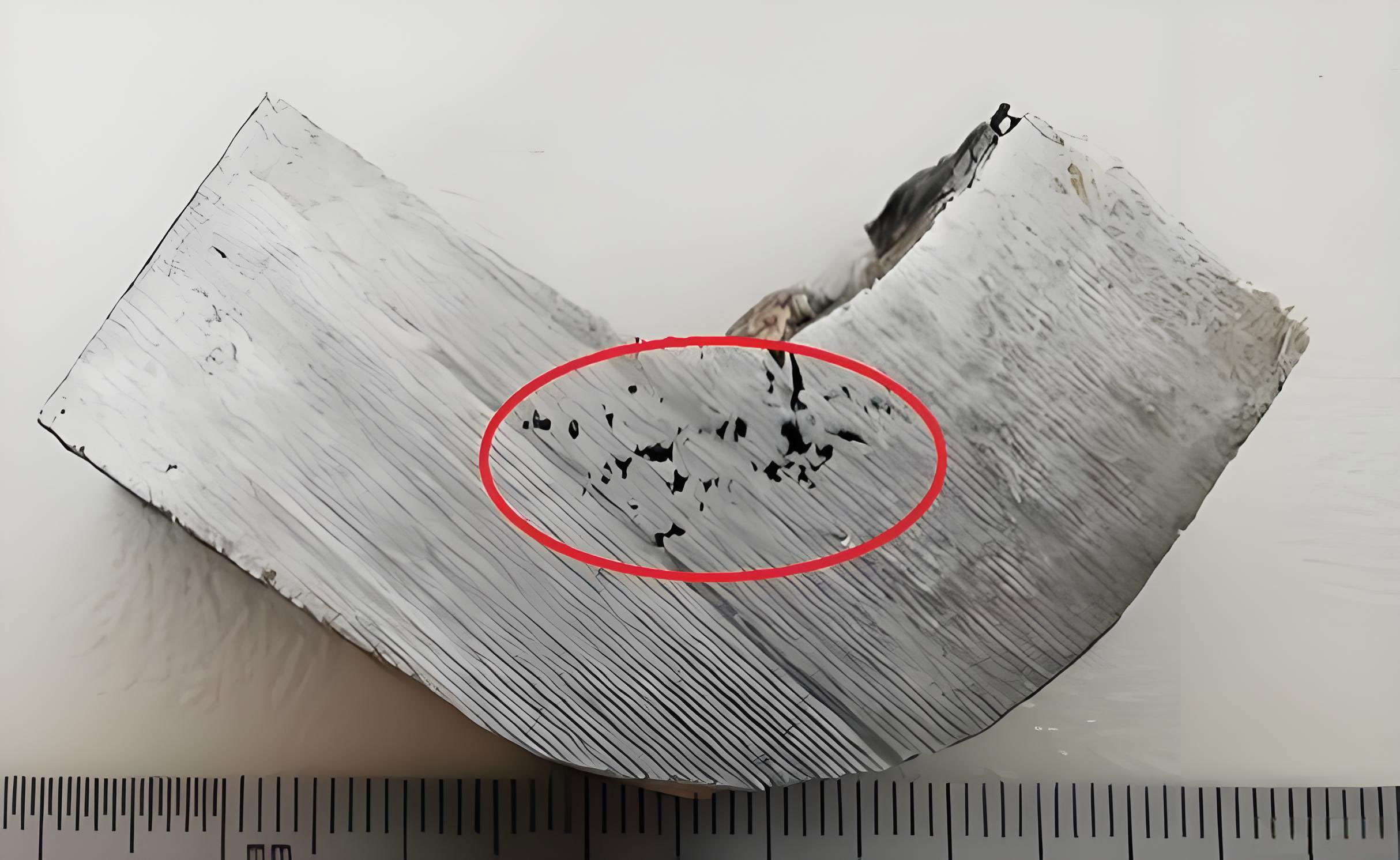
Metallographic analysis confirmed the defects were interdendritic shrinkage porosity, i.e., ‘shrinkage in casting’.
Stage 1 Analysis and Initial Fix Attempt
1. Fire-Deck Bosses: Three isolated bosses on the fire-deck, despite having feeding risers connected to the main feeder, showed ‘shrinkage in casting’. Analysis suggested these small, isolated “islands” of metal were being overheated by the massive heat influx from the large main feeder. This disrupted the local thermal field, preventing clean directional solidification from the boss tip down to its base/feeder connection. The thermal gradient was ‘chaotic,’ leading to isolated micro-shrinkage pockets.
2. Tappet Bore near Injector: The ‘shrinkage in casting’ here was attributed to an undersized feeder neck connecting the tappet bore area to the injector bore feeder. The neck solidified too quickly, acting as a choke and severing the feeding path prematurely. The required feeding flow for the tappet bore area, governed by the shrinkage volume \( V_{shrink} \) and feeding distance \( L \), was not met:
$$ Q_{required} \propto \beta \cdot V_{hot-spot} / t_{solidification} $$
where \( \beta \) is the volumetric shrinkage coefficient of the alloy. An undersized neck restricts flow \( Q \).
Initial Corrective Action (Hand-modified core trial):
- The feeding channels to the three fire-deck bosses were manually blocked on the sand core using ceramic paste.
- The feeder neck for the injector/tappet area was manually enlarged to extend closer to the tappet bore.
Trial Result (36 pieces): The ‘shrinkage in casting’ defect rate on the targeted surfaces dropped dramatically to ~3.45%. This seemed to validate the hypothesis: isolating the bosses from excessive feeder heat and enlarging the critical feeder neck resolved the problem.
Stage 2: New Problem Emergence from the “Fix”
Based on the successful trial, the permanent tooling for the sand core was modified accordingly. However, a high-volume trial of 200+ pieces revealed a catastrophic new issue: water jacket leakage at a rate exceeding 50%.
Pressure testing and X-ray analysis pinpointed the leakage to a specific area on the water jacket wall. This area was located between the two injector bore feeders and, critically, was directly beneath the central fire-deck boss whose feeder had been removed in the modification.
Root Cause of Leakage: The leakage zone was a new, unintended thermal center. By removing the feeder from the central boss, we eliminated its source of feed metal. However, this boss, connected to a thick section of the casting (the water jacket wall), still required feeding. During solidification, it now tried to draw liquid from the surrounding areas, primarily the water jacket wall itself. This created a “internal feeding” or “suction” effect, pulling shrinkage porosity (‘shrinkage in casting’) into the water jacket wall structure, making it leak.
Essentially, the casting itself became a poor internal feeder for the isolated hot spot, transferring the ‘shrinkage in casting’ defect from the machined deck surface into the pressure-containing wall.
Stage 3: Final Integrated Solution
The lesson was clear: a one-dimensional fix can create new problems. The solution required a holistic, targeted feeding strategy. The approach was revised:
- Targeted, Minimal Feeding for the Leakage Zone: Instead of the original large feeder or no feeder, two small, dedicated feeder “pipes” were added from the top of the casting directly down to the thick section of the water jacket wall that was leaking. These were designed using modulus calculations to provide *just enough* feed metal for that specific hot spot:
$$ (Modulus)_{New\;Feeder\;Pipe} \approx 1.2 \times (Modulus)_{Leaking\;Wall\;Section} $$ - Maintained Isolation for Other Bosses: The feeding to the other two fire-deck bosses (which were not causing leakage) remained blocked, as planned.
- Maintained Enlarged Feeder Neck for Tappet Bore: The successful modification for the tappet bore area was kept.
This final configuration provided a precise, ‘surgical’ feeding solution. It supplied the necessary liquid to the true thermal center causing leakage (the water jacket wall under the central boss) without reintroducing excessive heat that would cause ‘shrinkage in casting’ on the boss surface itself. The outcome was the elimination of both the original fire-deck/tappet bore ‘shrinkage in casting’ and the subsequent leakage problem.
Conclusions and Foundry Principles for Managing Shrinkage in Casting
The journey through these cases reinforces that ‘shrinkage in casting’ is not a random occurrence but a direct consequence of the solidification thermal field. Prevention requires a systems approach.
| Principle | Technical Objective | Practical Methods |
|---|---|---|
| Directional Solidification | Establish a stable thermal gradient from casting extremities to feeders. | Proper gating/risering design, use of chills, controlled mold cooling. |
| Thermal Management | Control the mold temperature field precisely. | Instrumented mold with cooling lines, thermal imaging, use of insulation/coatings on feeders. |
| Adequate Feeding | Ensure liquid metal supply lasts longer than the section needing feed. | Feeder modulus > Casting modulus, sufficient feeder neck size, consider pressurization. |
| Holistic Analysis | Understand interactions within the entire casting-feeder system. | Use solidification simulation (if available), analyze failed castings systematically, consider second-order effects of any change. |
| Collaborative Design | Avoid unfeedable geometries from the start. | Early involvement of foundry in product design for manufacturability (DFM) reviews. |
A key takeaway is that solving ‘shrinkage in casting’ often involves balancing competing thermal demands. Blocking a feeder might solve surface shrinkage on one boss but can induce internal ‘shrinkage in casting’ and leakage elsewhere. The foundry engineer must think in terms of the entire three-dimensional thermal field and the interconnectedness of all sections of the casting.
Furthermore, process stability is critical. Even a well-designed mold can produce ‘shrinkage in casting’ if key process variables like pouring temperature, metal quality, or mold temperature control drift outside their optimal windows. The relationship is complex, but controlling the solidification time \( t \) and thermal gradient \( G \) is essential. The condition for sound solidification can be conceptualized as maintaining a sufficient gradient-to-solidification-time ratio to avoid underfed conditions:
$$ G / \sqrt{t} \geq K $$
where \( K \) is a constant for a given alloy and defect type. Process instability reduces \( G \) or increases \( t \), pushing the system towards ‘shrinkage in casting’.
In conclusion, defeating ‘shrinkage in casting’ is a fundamental task for producing high-quality aluminum castings. It requires a deep understanding of solidification principles, meticulous attention to thermal management in both tooling and process, and a disciplined, holistic approach to problem-solving where every corrective action is evaluated for its system-wide impact. Each defect investigation, successful or otherwise, builds the empirical knowledge necessary to master the complex dance of heat and metal that is the casting process.