
In the field of advanced materials engineering, particularly for aerospace and power generation applications, the integrity of cast components is paramount. I have dedicated significant research efforts to understanding defect formation during solidification, with a focus on shrinkage in casting. Shrinkage porosity, a common defect in metal castings, arises from inadequate liquid metal feeding during solidification, leading to voids that compromise mechanical properties. This issue is especially critical in high-performance materials like nickel-based single crystal superalloys, which are essential for turbine blades in jet engines and gas turbines due to their exceptional high-temperature strength, creep resistance, and thermal stability. The presence of shrinkage in casting can drastically reduce the fatigue life and load-bearing capacity of these components, impacting safety and efficiency. Therefore, developing robust methods to predict and mitigate shrinkage in casting is a key objective in both academia and industry.
The formation of shrinkage in casting is a complex phenomenon influenced by multiple factors, including alloy composition, thermal properties, process parameters, and geometric design. During directional solidification, which is used to produce single crystal structures, the progressive development of dendritic networks can impede liquid flow, trapping residual melt and preventing feeding to the dendrite roots. This results in microporosity or shrinkage porosity, often concentrated in last-to-freeze regions. While previous studies have examined the effects of elements like Al, Ti, Co, and Cr on shrinkage susceptibility, as well as the role of solidification rate and temperature gradient, less attention has been paid to how component geometry—such as rejoined or platform structures in turbine blades—affects shrinkage in casting. These geometric features, common in nozzle guide vanes and multi-segment blades, can create localized feeding challenges, making them prone to defects. To address this, numerical simulation tools like ProCAST, based on finite element analysis, offer a powerful means to visualize solidification sequences, predict defect locations, and optimize process parameters without costly trial-and-error experiments. In this work, I employ ProCAST to investigate shrinkage porosity formation in a model casting with rejoined platforms, analyzing the interplay between geometry and withdrawal rate on shrinkage in casting. The goal is to provide insights that enhance defect control in single crystal superalloy castings.
My approach centers on a comprehensive numerical model that replicates the directional solidification process. The material of interest is a second-generation nickel-based single crystal superalloy, DD6, with a nominal composition designed for high-temperature performance. Its chemical makeup is summarized in Table 1, highlighting elements that influence solidification range and feeding characteristics. Shrinkage in casting is particularly sensitive to alloys with wide freezing ranges, as prolonged mushy zone existence hampers feeding.
| Cr | Co | Mo | W | Ta | Re | Nb | Al | Hf | C | Ni |
|---|---|---|---|---|---|---|---|---|---|---|
| 4.3 | 9.0 | 2.0 | 8.0 | 7.5 | 2.0 | 0.5 | 5.6 | 0.1 | 0.006 | Bal. |
The casting geometry, inspired by actual turbine blade features, includes a rejoined platform structure that mimics the cross-sectional transitions found in guide vanes. As shown in the model schematic, the design consists of a starter block, a grain selector, multiple rejoined platforms, and a riser to aid feeding. The platforms represent regions where the cross-section expands and contracts, creating potential hotspots for shrinkage in casting. To simulate this, I created a 3D model using CAD software, ensuring symmetry to avoid bias from asymmetric temperature fields. The mold assembly, comprising a ceramic shell, heating system, radiation baffles, and water-cooled chill, was modeled to capture the thermal environment of a Bridgman-type directional solidification furnace. The finite element mesh was generated with care: the furnace components were discretized using surface elements for radiative heat transfer efficiency, while the casting and mold were meshed with volumetric elements to resolve temperature and flow fields accurately. This dual meshing strategy balances computational cost and precision, essential for predicting shrinkage in casting.
The ProCAST software solves coupled equations for heat transfer, fluid flow, and solidification kinetics. The governing heat conduction equation with phase change is:
$$ \rho c_p \frac{\partial T}{\partial t} = \nabla \cdot (k \nabla T) + L \frac{\partial f_s}{\partial t} $$
where \( \rho \) is density, \( c_p \) is specific heat, \( k \) is thermal conductivity, \( T \) is temperature, \( t \) is time, \( L \) is latent heat of fusion, and \( f_s \) is solid fraction. The evolution of \( f_s \) is described by a Scheil-type model or lever rule, depending on alloy assumptions. For shrinkage in casting prediction, ProCAST incorporates criteria based on feeding flow and pressure drop. The Niyama criterion, often used to assess shrinkage susceptibility, relates the temperature gradient \( G \) and cooling rate \( \dot{T} \):
$$ N_y = \frac{G}{\sqrt{\dot{T}}} $$
Lower \( N_y \) values indicate higher risk of shrinkage in casting. Additionally, the software tracks liquid metal flow through the mushy zone using Darcy’s law:
$$ \mathbf{u} = -\frac{K}{\mu} (\nabla P – \rho \mathbf{g}) $$
where \( \mathbf{u} \) is velocity, \( K \) is permeability (dependent on dendritic structure), \( \mu \) is viscosity, \( P \) is pressure, \( \rho \) is density, and \( \mathbf{g} \) is gravity. Blockage of flow channels leads to pressure drop and void formation, i.e., shrinkage in casting. The simulation parameters, derived from typical industrial practice, are listed in Table 2. Key settings include initial melt temperature, boundary conditions for radiation and convection, and interfacial heat transfer coefficients. The withdrawal process is simulated by moving the mold relative to the furnace at specified rates, directly influencing thermal gradients and solidification fronts.
| Parameter | Value |
|---|---|
| Initial Melt Temperature | 1550 °C |
| Water-Cooled Chill Temperature | 20 °C |
| Heater Temperature | 1550 °C |
| Heater Emissivity | 0.8 |
| Ceramic Mold Emissivity | 0.7 |
| Furnace Internal Emissivity | 0.3 |
| Chill Plate Emissivity | 0.2 |
| Cooling Water Heat Transfer Coefficient | 2000 W·m⁻²·K⁻¹ |
| Cooling Water Temperature | 20 °C |
| Alloy-Mold Interface Heat Transfer Coefficient | 1000 W·m⁻²·K⁻¹ |
| Alloy-Chill Interface Heat Transfer Coefficient | 3000 W·m⁻²·K⁻¹ |
| Mold-Chill Interface Heat Transfer Coefficient | 20 W·m⁻²·K⁻¹ |
My simulation results reveal detailed insights into shrinkage in casting formation. As solidification progresses, the temperature distribution and solid fraction evolution show that each rejoined platform acts as a thermal bottleneck. The platforms solidify from the sides inward, with the last-to-freeze zone located near the top-center region. This is where liquid feeding becomes most difficult, leading to shrinkage in casting. The visualizations indicate that early solidification at the platform edges blocks the feeding paths for the interior liquid, causing isolated pools that shrink upon freezing. The riser, intended to provide feed metal, cannot compensate for these blocked channels due to the geometry-induced constraints. Thus, shrinkage in casting is inherently linked to local solidification sequences and channel accessibility.
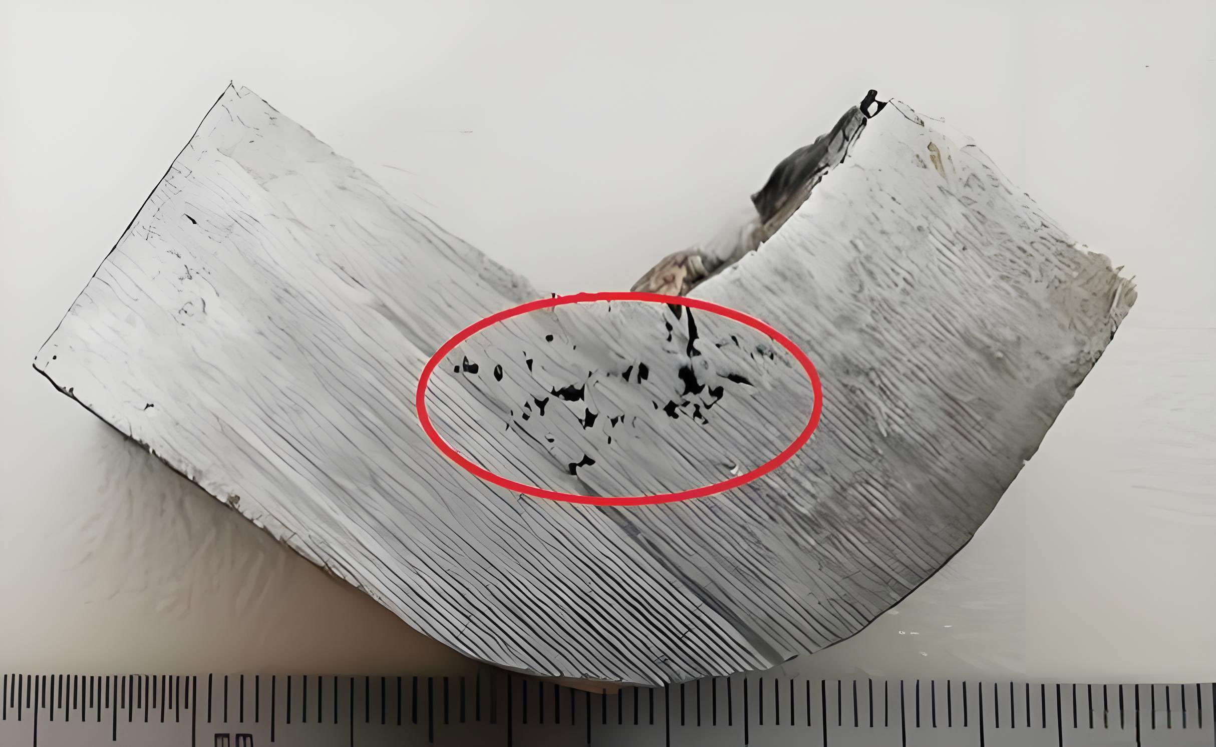
The effect of withdrawal rate on shrinkage in casting is pronounced. I simulated three rates: 60 µm/s, 100 µm/s, and 150 µm/s, representing slow, moderate, and fast solidification conditions. The results, summarized in Table 3, show that as withdrawal rate increases, the extent and severity of shrinkage in casting increase. At 60 µm/s, shrinkage porosity is concentrated in small, dense clusters within the platform last-freeze zones. At 100 µm/s, the porosity becomes more dispersed, covering a larger area. At 150 µm/s, the shrinkage in casting spreads further, with larger pore sizes and greater volumetric fraction. This trend correlates with the shape of the solidification front. At lower rates, the thermal gradient is steeper, and the isotherms are relatively flat, promoting directional feeding. Higher rates reduce the gradient and cause the solid-liquid interface to become more concave, especially in the platform regions, as described by the interface curvature equation:
$$ \kappa = \frac{1}{R} \propto \frac{v}{\alpha} $$
where \( \kappa \) is curvature, \( R \) is radius of curvature, \( v \) is withdrawal rate, and \( \alpha \) is thermal diffusivity. Increased concavity narrows the feeding channels earlier, exacerbating shrinkage in casting. The solid fraction profiles confirm that faster withdrawal leads to a wider mushy zone, where permeability drops rapidly according to the Kozeny-Carman relation:
$$ K = \frac{(1 – f_s)^3}{c f_s^2} $$
with \( c \) as a constant. This reduces liquid flow and increases pore formation. Thus, controlling withdrawal rate is crucial to managing shrinkage in casting.
| Withdrawal Rate (µm/s) | Shrinkage Porosity Location | Relative Area Affected | Pore Size Trend |
|---|---|---|---|
| 60 | Localized in platform centers | Small | Fine, clustered |
| 100 | Dispersed across platforms | Moderate | Medium, scattered |
| 150 | Widespread in platforms and adjacent areas | Large | Coarse, interconnected |
Further analysis involves the Niyama criterion values across the casting. I computed \( N_y \) for each scenario, finding that regions with \( N_y < 1 \) °C·s¹/²·mm⁻¹ consistently correspond to shrinkage in casting sites. This validates the use of such criteria for defect prediction. The mathematical integration of these factors underscores that shrinkage in casting is not random but follows predictable patterns based on thermal parameters. Additionally, the geometry effect can be quantified through a feeding distance model. For narrow platforms, the feeding distance \( d_f \) is limited by the channel width \( w \) and solid fraction threshold:
$$ d_f = \frac{\Delta P \cdot K}{\mu \cdot v_f} $$
where \( \Delta P \) is pressure drop and \( v_f \) is feeding velocity. When \( d_f \) is less than the platform length, shrinkage in casting occurs. My simulations show that for the modeled platforms, \( d_f \) is insufficient at higher withdrawal rates, aligning with the observed defects.
In discussion, the implications of these findings for industrial casting are significant. Shrinkage in casting can be mitigated by optimizing both design and process. Geometrically, enlarging platform cross-sections or adding feeders near last-freeze zones can improve feeding. Process-wise, lowering withdrawal rates enhances thermal gradients but may reduce productivity; thus, a balance must be struck. Advanced techniques like active cooling or electromagnetic stirring could alter flow dynamics to reduce shrinkage in casting. Compared to prior studies that focus on alloy chemistry, this work highlights how geometry-induced flow blockage is a dominant factor in shrinkage formation, especially for complex castings like turbine blades. The numerical approach here provides a roadmap for virtual prototyping, allowing engineers to test modifications before physical trials, saving time and cost while minimizing shrinkage in casting.
In conclusion, my numerical investigation using ProCAST software elucidates the mechanisms of shrinkage porosity formation in nickel-based single crystal superalloy castings with rejoined platforms. Shrinkage in casting primarily occurs in last-to-solidify regions of platforms, driven by geometric constraints that block liquid metal feeding and by process parameters like withdrawal rate that affect interface morphology. Higher withdrawal rates increase interface concavity and mushy zone width, aggravating shrinkage in casting. These insights emphasize the need for integrated design-process optimization to control shrinkage in casting. Future work could explore multi-scale modeling linking macroscopic shrinkage to microscopic pore nucleation, or machine learning algorithms for rapid defect prediction. Ultimately, reducing shrinkage in casting is vital for enhancing the reliability and performance of critical aerospace components, contributing to safer and more efficient propulsion systems.