
In the realm of die-casting production, casting holes represent a pervasive and recurrent defect that significantly compromises product integrity. The rejection rate of castings due to unqualified casting holes can account for 25% to 80% of total scrap, leading to substantial economic losses. Consequently, mitigating and eliminating casting holes is paramount for ensuring casting quality. Given the inherent nature of die-casting—where aluminum alloy is shaped under conditions of high temperature, high speed, and high pressure—the presence of internal casting holes is often unavoidable. Thus, continuous process adjustments are essential to ameliorate casting hole-related issues. Through production observations, it has been noted that casting holes frequently concentrate near the gate plane of components. Analysis of the production process suggests that various parameters exert considerable influence on the formation of casting holes at these locations, including the quantity of plunger lubricant, die temperature, injection speed, and high-speed start point. Identifying the most impactful factors provides a directive for process optimization to address quality concerns. This article, drawing from practical production cases, aims to validate the effects of different process parameters on casting holes, employing a first-person perspective to detail experimental methodologies, data analysis, and theoretical insights.
Casting holes, often manifesting as gas entrapments or shrinkage cavities, are detrimental to the mechanical properties and surface finish of die-cast parts. The formation of casting holes is intricately linked to process dynamics, where improper settings can exacerbate gas inclusion or solidification defects. The primary objective of this investigation is to empirically assess how specific process variables influence the incidence and severity of casting holes in aluminum die-castings. By systematically varying parameters and evaluating outcomes, we seek to establish guidelines for minimizing casting holes, thereby enhancing product yield and performance.
Experimental Objectives and Methodology
The core intent of these experiments is to verify the impact of key die-casting process parameters on casting holes. The focus is on four factors: plunger lubricant usage, high-speed injection velocity, high-speed start position, and die temperature. Each factor is isolated and tested while maintaining other variables constant to ensure result validity. The evaluation metric involves machining the cast samples to expose the gate plane and inspecting for casting holes using visual examination and measurement tools, such as film gauges, to quantify hole size and frequency.
General experimental procedure includes: preheating the die to stable production conditions, discarding initial shots to eliminate transients, collecting samples under specific parameter sets, machining the samples to reveal subsurface features, and analyzing the machined surfaces for casting holes. Data are recorded in tabular form, and theoretical models are employed to interpret trends. The term “casting holes” is emphasized throughout to underscore the defect under study.
Influence of Plunger Lubricant on Casting Holes
Plunger lubricant, essential for reducing friction and wear in the shot sleeve, can inadvertently contribute to casting holes if excessive. The lubricant, when not fully volatilized during injection, may become entrapped in the molten aluminum, leading to gas porosity or slag inclusions upon solidification.
Experimental Method: Tests were conducted on a consistent die-casting machine with fixed parameters. The plunger lubricant flow rate was adjusted via a control valve, set at two distinct levels: position “3” (lower flow) and position “4” (higher flow). For each setting, six shots were produced after stabilization, and the biscuit appearance was observed as an indirect indicator. Samples were then machined and inspected for casting holes.
Observations and Data: At valve position “3”, the biscuit exhibited a lighter color with minimal dark spots, suggesting moderate lubricant usage. After machining, four out of six samples showed no casting holes, while two had minor, isolated casting holes (diameter < 0.5 mm). In contrast, at position “4”, the biscuit darkened significantly, indicating excess lubricant. Here, five out of six samples contained casting holes, with diameters exceeding 1 mm in some cases and increased hole frequency, including clustered casting holes.
The results are summarized in Table 1, highlighting the correlation between lubricant quantity and casting hole severity.
| Valve Position | Biscuit Color | Samples with Casting Holes | Max Hole Diameter (mm) | Hole Frequency |
|---|---|---|---|---|
| 3 (Lower Flow) | Light, Few Dark Spots | 2 out of 6 | ~0.5 | Low, Isolated |
| 4 (Higher Flow) | Dark, Extensive Staining | 5 out of 6 | >1.0 | High, Clustered |
The increase in casting holes with higher lubricant flow can be modeled by considering the volume of non-volatilized lubricant \( V_l \) that enters the melt. Assuming a linear relationship, the gas content \( G \) contributing to casting holes might be approximated as:
$$ G = k \cdot Q_l $$
where \( Q_l \) is the lubricant flow rate and \( k \) is a process-dependent constant. Excessive \( Q_l \) elevates \( G \), raising the probability of casting holes formation.
Conclusion: Higher plunger lubricant usage correlates with increased casting hole occurrence and size. Optimal lubricant flow should balance lubrication efficacy with minimal gas entrapment, guided by biscuit coloration.
Impact of High-Speed Injection Velocity on Casting Holes
Injection velocity during the high-speed phase critically affects melt flow dynamics and gas entrapment. Low velocities may prolong residence time in the shot sleeve, promoting shrinkage, while excessive velocities can induce turbulence and air ingestion.
Experimental Method: The high-speed velocity was varied from 2.4 m/s to 3.4 m/s in increments of 0.2 m/s, with other parameters constant. For each velocity, eight samples were collected after a 30-shot warm-up and stabilization period. Machined surfaces were examined, and casting holes were measured.
Observations and Data: As velocity increased from 2.4 m/s to 3.2 m/s, casting hole frequency and size generally decreased. However, at 3.4 m/s, casting holes reappeared with larger diameters. Specifically:
- At 2.4 m/s and 2.6 m/s: Casting holes were often clustered and large (diameter > 1 mm).
- At 2.8 m/s: Fewer casting holes, but some exceeded 0.5 mm.
- At 3.0 m/s and 3.2 m/s: Casting holes were minimal (≤2 per sample) and small (diameter ≤ 0.5 mm).
- At 3.4 m/s: Some samples showed casting holes > 1 mm.
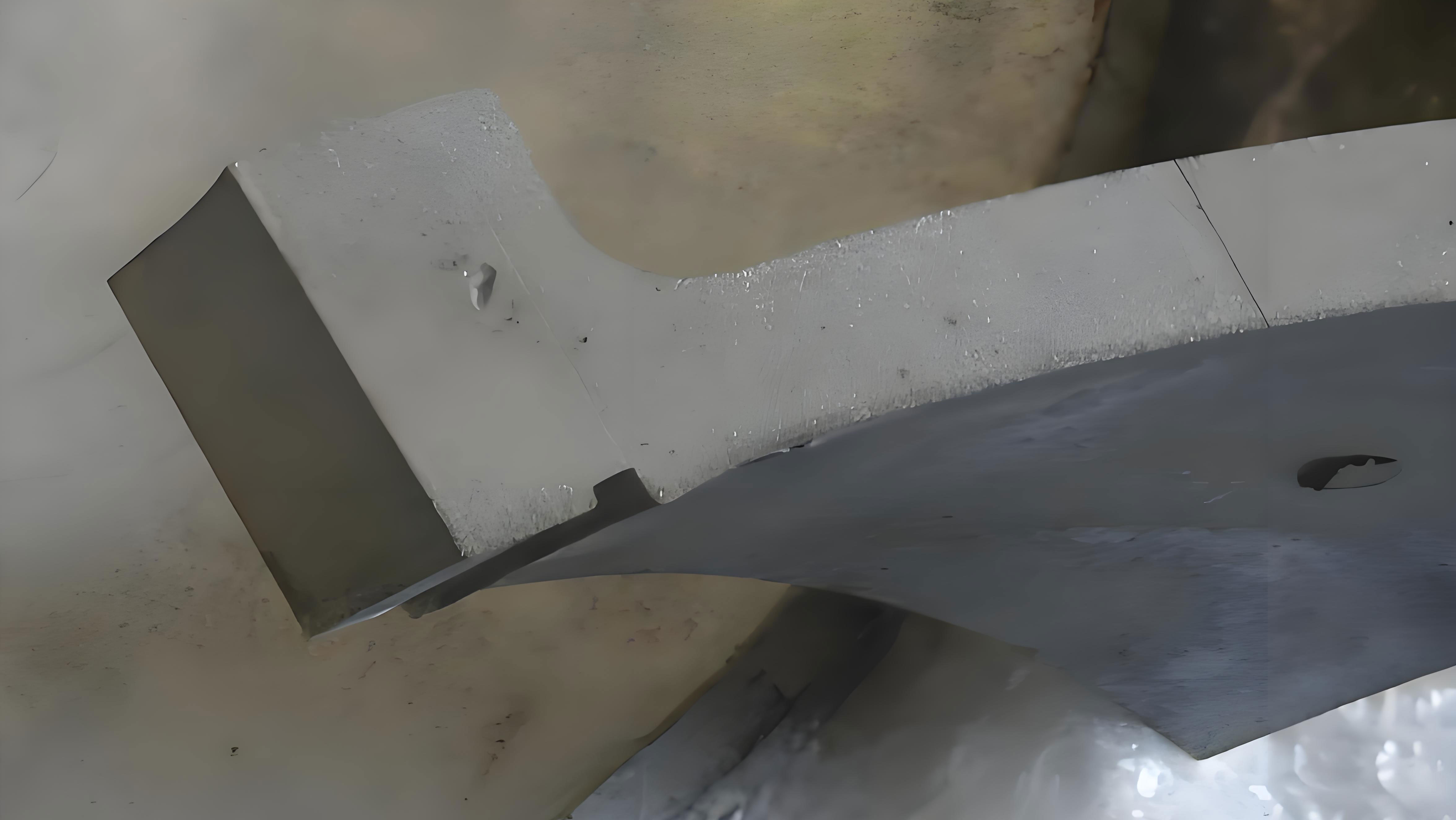
Table 2 quantifies these trends, and Figure 1 illustrates the relationship between velocity and casting hole quality.
| High-Speed Velocity (m/s) | Samples with Acceptable Casting Holes (≤0.5 mm) | Average Number of Casting Holes per Sample | Maximum Hole Diameter (mm) |
|---|---|---|---|
| 2.4 | 1 out of 8 | 3.5 | 1.2 |
| 2.6 | 2 out of 8 | 3.0 | 1.1 |
| 2.8 | 4 out of 8 | 2.0 | 0.7 |
| 3.0 | 7 out of 8 | 0.8 | 0.5 |
| 3.2 | 7 out of 8 | 0.6 | 0.5 |
| 3.4 | 3 out of 8 | 2.5 | 1.3 |
The behavior can be explained through fluid dynamics. The Reynolds number \( Re \) for flow in the shot sleeve is given by:
$$ Re = \frac{\rho v D}{\mu} $$
where \( \rho \) is melt density, \( v \) is velocity, \( D \) is sleeve diameter, and \( \mu \) is dynamic viscosity. At low \( v \), \( Re \) is low, leading to laminar flow but extended cooling, which may foster shrinkage casting holes. At moderate \( v \) (3.0-3.2 m/s), \( Re \) achieves an optimal range that minimizes both shrinkage and turbulence. At high \( v \), \( Re \) becomes excessive, causing turbulent flow that entraps air, thus generating gas-related casting holes.
Additionally, the solidification time \( t_s \) can be estimated using Chvorinov’s rule:
$$ t_s = C \left( \frac{V}{A} \right)^n $$
where \( V \) is volume, \( A \) is surface area, \( C \) is a constant, and \( n \) is an exponent. Lower velocities increase \( t_s \) in the sleeve, allowing more time for gas dissolution and shrinkage, potentially worsening casting holes.
Conclusion: An optimal high-speed velocity range (3.0-3.2 m/s) minimizes casting holes by balancing flow stability and cooling effects. Deviations outside this range increase casting hole propensity.
Effect of High-Speed Start Point on Casting Holes
The high-speed start point, defining when the injection switches from slow to high speed, influences melt front stability and air evacuation. A delayed start may lengthen slow-phase duration, leading to premature solidification and poor feeding.
Experimental Method: High-speed start points were tested at 360 mm, 370 mm, and 380 mm from the shot sleeve beginning, with other parameters fixed. Eight samples per setting were machined and evaluated for casting holes.
Observations and Data: Casting hole occurrence escalated with increasing start point distance. At 360 mm, only one sample exhibited a minor casting hole (0.4 mm). At 370 mm, up to four casting holes per sample were found, with diameters reaching 0.8 mm. At 380 mm, casting holes were more prevalent and larger, exceeding 1 mm in some instances.
Table 3 summarizes the data, indicating a clear trend.
| High-Speed Start Point (mm) | Samples with Casting Holes | Average Hole Diameter (mm) | Maximum Hole Diameter (mm) |
|---|---|---|---|
| 360 | 1 out of 8 | 0.1 | 0.4 |
| 370 | 6 out of 8 | 0.4 | 0.8 |
| 380 | 8 out of 8 | 0.7 | 1.2 |
The increase in casting holes with later start points can be attributed to prolonged low-speed phase, which extends the time \( t_{low} \) for heat loss. The temperature drop \( \Delta T \) in the melt front can be expressed as:
$$ \Delta T = \alpha \cdot t_{low} $$
where \( \alpha \) is a cooling coefficient. A larger \( t_{low} \) leads to greater \( \Delta T \), causing partial solidification that hinders melt feeding and promotes shrinkage casting holes. Moreover, hydrogen solubility decreases with temperature, potentially releasing gas that forms casting holes.
Mathematically, the fraction of solid \( f_s \) formed during the low-speed phase can be approximated by:
$$ f_s = 1 – \exp\left(-\beta t_{low}\right) $$
where \( \beta \) is a solidification rate constant. Higher \( f_s \) reduces fluidity, increasing the likelihood of casting holes due to inadequate cavity filling and gas trapping.
Conclusion: Earlier high-speed start points (e.g., 360 mm) reduce casting holes by limiting premature cooling and solidification. Delayed starts exacerbate casting hole formation, particularly shrinkage-related casting holes.
Role of Die Temperature in Casting Hole Formation
Die temperature governs heat extraction rates, affecting solidification patterns and gas behavior. Low die temperatures accelerate cooling, potentially creating shrinkage and gas porosity, while appropriate temperatures promote directional solidification and gas escape.
Experimental Method: Two die temperature ranges were assessed: below 160°C and above 160°C (up to 224°C), adjusted via cooling water flow. Temperature was monitored using a thermal imager. Eight samples per range were produced, machined, and inspected for casting holes.
Observations and Data: At die temperatures below 160°C, every sample contained casting holes, with numerous large holes (diameter > 1 mm) and high frequency. Conversely, at temperatures above 160°C, casting holes were significantly reduced, with ≤2 small holes (diameter ≤ 0.4 mm) per sample.
Table 4 contrasts the outcomes, underscoring the importance of thermal management.
| Die Temperature Range (°C) | Samples with Casting Holes | Average Number of Casting Holes per Sample | Maximum Hole Diameter (mm) |
|---|---|---|---|
| < 160 | 8 out of 8 | 5.2 | 1.5 |
| > 160 (≤224) | 3 out of 8 | 0.6 | 0.4 |
The influence of die temperature \( T_d \) on casting holes can be modeled through heat transfer. The cooling rate \( \dot{T} \) is proportional to the temperature difference between melt \( T_m \) and die \( T_d \):
$$ \dot{T} = h (T_m – T_d) $$
where \( h \) is the heat transfer coefficient. Lower \( T_d \) increases \( \dot{T} \), leading to rapid solidification that may trap gas and create shrinkage casting holes. Optimal \( T_d \) reduces \( \dot{T} \), allowing gases to escape and promoting better feeding.
Furthermore, the Niyama criterion, often used to predict shrinkage porosity, can be adapted for casting holes. It relates thermal gradient \( G \) and cooling rate \( \dot{T} \):
$$ N_y = \frac{G}{\sqrt{\dot{T}}} $$
Low \( N_y \) values indicate susceptibility to shrinkage casting holes. Elevated die temperatures improve \( G \) and moderate \( \dot{T} \), thereby increasing \( N_y \) and reducing casting holes.
Conclusion: Maintaining die temperature above 160°C (within operational limits) markedly diminishes casting hole incidence by moderating cooling rates and enhancing melt flow.
Comprehensive Analysis and Practical Implications
The collective findings underscore that casting holes are highly sensitive to process parameters. Each factor—plunger lubricant, high-speed velocity, high-speed start point, and die temperature—interacts with the die-casting environment to influence gas entrapment and solidification defects. To synthesize the results, a multivariate approach can be considered, where the probability \( P \) of casting hole formation is a function of these variables:
$$ P = f(Q_l, v, s, T_d) $$
where \( Q_l \) is lubricant flow, \( v \) is high-speed velocity, \( s \) is high-speed start point, and \( T_d \) is die temperature. Empirical data suggest that \( P \) increases with \( Q_l \) and \( s \), exhibits a minimum at intermediate \( v \), and decreases with higher \( T_d \).
For process optimization, a response surface methodology could be employed to model casting hole response. However, based on this study, recommended settings include: minimized lubricant flow sufficient for lubrication, high-speed velocity of 3.0-3.2 m/s, early high-speed start (e.g., 360 mm), and die temperature maintained above 160°C. These adjustments collectively mitigate casting holes, improving product quality.
It is noteworthy that casting holes may also arise from other factors like alloy composition, melt cleanliness, and venting design, but these were beyond the scope of this investigation. Future work could integrate these aspects for a holistic view.
Final Conclusions
Through systematic experimentation, the following conclusions are drawn regarding casting holes in die-cast aluminum components:
- Plunger Lubricant: Excessive usage correlates with higher casting hole frequency and size, as unvaporized lubricant introduces gas. Optimal flow should be gauged via biscuit coloration.
- High-Speed Velocity: An intermediate range (3.0-3.2 m/s) minimizes casting holes by balancing flow stability and cooling. Lower velocities promote shrinkage casting holes, while higher ones induce turbulence-related casting holes.
- High-Speed Start Point: Earlier start points reduce casting holes by limiting premature solidification. Delayed starts extend cooling, increasing shrinkage and gas-related casting holes.
- Die Temperature: Temperatures above 160°C significantly reduce casting holes by slowing cooling rates, allowing better gas evacuation and feeding.
In practice, continuous monitoring and adjustment of these parameters are crucial for controlling casting holes. The insights provided here offer a foundation for die-casting engineers to troubleshoot and optimize processes, ultimately reducing scrap rates and enhancing economic efficiency. The persistent challenge of casting holes necessitates ongoing research, but with careful parameter management, their impact can be substantially alleviated.