
In my experience as a foundry engineer, addressing defects in cast components is critical for maintaining production efficiency and product quality. Recently, I encountered a significant issue with casting holes, specifically sand inclusions and gas porosity, in gray iron motor end covers. These casting holes led to a scrap rate of up to 30%, severely impacting the manufacturing schedule for motors used in mining equipment such as roadheaders, shearers, and scraper conveyors. This article details my first-person analysis and解决方案, focusing on how I tackled these casting holes through process modifications. I will elaborate on the defect characteristics, casting工艺, root cause analysis, and implemented measures, emphasizing the importance of controlling various parameters to minimize casting holes. Throughout this discussion, I will incorporate tables and formulas to summarize key points, ensuring a comprehensive understanding of how casting holes can be mitigated in类似 applications.
Cast motor end covers are essential components that house and protect电机 internals. Their production via casting offers cost-effectiveness and simplicity, but defects like casting holes can arise due to multiple factors. In this case, the casting holes manifested as sand inclusions on the vertical faces near the core and gas porosity on the upper parting surface, with additional surface roughness on the outer circumference. These casting holes not only compromised structural integrity but also increased post-processing costs. My goal was to reduce the scrap rate to a reasonable level by systematically addressing the sources of these casting holes. I will begin by describing the缺陷 in detail, followed by an overview of the casting工艺, a deep dive into the analysis of casting holes, the specific措施 I implemented, and the outcomes. Along the way, I will use mathematical models and empirical data to support my approach, highlighting how each factor contributes to the formation of casting holes.
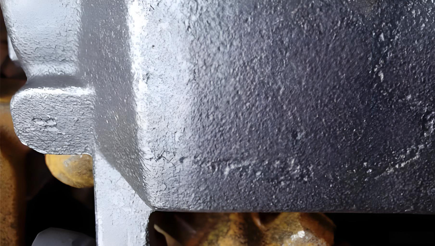
Defect Localization and Characteristics of Casting Holes
The casting holes in the motor end covers were primarily of two types: sand inclusions and gas porosity. Sand inclusions appeared as embedded sand particles on the inner vertical surfaces adjacent to the core, while gas porosity manifested as small cavities on the top parting plane. The entire outer circumferential surface exhibited poor finish, indicating underlying issues with the mold surface. To clarify, casting holes like these often result from inadequate mold strength, improper gating, or insufficient venting. I observed that the sand inclusions were likely due to砂粒 dislodging during metal pouring, whereas gas porosity stemmed from trapped gases from the mold or metal. These casting holes are critical defects that can lead to leakage, reduced mechanical strength, and failure in service. The following table summarizes the defect types and their locations, emphasizing the prevalence of casting holes in specific areas:
| Defect Type | Location on End Cover | Possible Causes | Impact on Quality |
|---|---|---|---|
| Sand Inclusions (Casting Holes) | Vertical faces near core side | Low face sand strength, improper coating | Surface roughness, potential stress concentrators |
| Gas Porosity (Casting Holes) | Upper parting surface | Inadequate venting, high gas evolution | Internal voids, reduced density |
| General Surface Roughness | Outer circumference | Poor face sand quality, erosion during pouring | Aesthetic issues, may harbor cracks |
The presence of these casting holes prompted a thorough review of the casting工艺. It’s essential to understand that casting holes can originate from multiple stages in the process, and a holistic approach is necessary for effective resolution. In my analysis, I considered factors such as sand properties, gating design, and venting arrangements, all of which play a role in the formation of casting holes.
Casting Process Overview for Motor End Covers
The casting工艺 employed for the motor end covers was a conventional green sand molding method using two-part flasks. This approach was chosen for its simplicity and suitability for批量 production. The process involved several key steps: pattern making, molding, core making, gating system design, and pouring. Each step has parameters that, if not optimized, can lead to casting holes. I oversaw the entire process to identify weak points contributing to casting holes.
First, the patterns were typically made of wood for flexibility, though aluminum metal patterns were used for high-volume runs to improve dimensional accuracy. The molding process utilized manual ramming with pneumatic vibrators, which, while labor-intensive, allowed for adaptability to various end cover sizes. The sand system comprised backing sand and face sand, with the face sand being critical for surface finish and resistance to casting holes. A water-based graphite coating was applied to the mold surface to enhance smoothness and prevent sand adherence. However, as I later discovered, issues with this coating contributed to casting holes.
The core was produced using wooden core boxes, ensuring accurate dimensions and incorporating ventilation channels to allow gas escape. Proper core design is vital to avoid casting holes caused by gas entrapment. The gating system was designed with tangential ingates to facilitate smooth metal flow into the cavity, minimizing turbulence that could dislodge sand and create casting holes. Riser and vent holes were placed on the parting surface to aid in feeding and gas expulsion. Despite these measures, casting holes persisted, indicating underlying deficiencies. The table below outlines the key process parameters and their intended functions, highlighting how deviations can lead to casting holes:
| Process Step | Parameters | Function | Risk for Casting Holes |
|---|---|---|---|
| Molding | Sand moisture content, ramming density | Provide mold strength and shape | Low strength leads to sand inclusions (casting holes) |
| Coating | Graphite quality, drying time | Improve surface finish and prevent erosion | Poor coating causes sand dislodgment (casting holes) |
| Gating Design | Ingate shape, size, and number | Control metal flow and minimize turbulence | Turbulence erodes sand, creating casting holes |
| Venting | Vent hole diameter, depth, and distribution | Allow gas escape during pouring | Insufficient venting causes gas porosity (casting holes) |
| Core Making | Core sand composition, vent channels | Form internal cavities and permit gas exit | Blocked vents lead to gas porosity (casting holes) |
From this overview, it became clear that multiple交互 factors could contribute to casting holes. My next step was to conduct a detailed root cause analysis, employing theoretical models and empirical observations to pinpoint the exact sources of these casting holes.
Root Cause Analysis of Casting Holes
To effectively address casting holes, I analyzed each potential cause based on the defect characteristics and process audit. Casting holes, whether sand inclusions or gas porosity, often result from a combination of material properties, process dynamics, and environmental conditions. I focused on five main areas: face sand strength, coating quality, gating system design, venting efficiency, and backing sand properties. Each of these can be linked to the formation of casting holes through physical and chemical mechanisms.
First, the face sand strength was suspected to be inadequate. The face sand must withstand the erosive forces of molten iron during pouring. If the strength is low,砂粒 can dislodge and become embedded in the casting, leading to sand inclusions—a type of casting hole. The strength of green sand depends on moisture content, clay content, and compaction. A common model for green sand strength relates it to these parameters. For instance, the compressive strength $\sigma_c$ can be expressed as a function of moisture content $w$ and clay content $c$:
$$ \sigma_c = k_1 \cdot c \cdot e^{-k_2 \cdot w} $$
where $k_1$ and $k_2$ are constants determined experimentally. In my case, I hypothesized that the moisture content was suboptimal, reducing $\sigma_c$ and increasing the risk of casting holes. Measurements showed that the face sand had a moisture content below the recommended range, compromising its ability to resist erosion.
Second, the water-based graphite coating was identified as a potential contributor to casting holes. The coating serves as a barrier between the sand and molten metal, preventing chemical reactions and sand adherence. If the coating quality is poor or not properly dried, it can fail to protect the surface, leading to sand dislodgment and casting holes. The drying process involves heat transfer, and insufficient drying time can leave residual moisture that vaporizes during pouring, creating gas pockets—another form of casting hole. The rate of drying can be modeled using Fick’s law of diffusion, where the moisture concentration $C$ changes over time $t$:
$$ \frac{\partial C}{\partial t} = D \nabla^2 C $$
with $D$ being the diffusion coefficient. In practice, I found that the coating was often applied hastily without adequate drying, exacerbating casting holes.
Third, the gating system design was reevaluated. The original ingates were straight, which could cause turbulent flow and high velocity, eroding the mold surface and generating casting holes. Turbulent flow increases the kinetic energy transfer to the sand, dislodging particles. The flow rate $Q$ through an ingate is given by:
$$ Q = A \cdot v $$
where $A$ is the cross-sectional area and $v$ is the velocity. For a given $Q$, a smaller $A$ leads to higher $v$, increasing erosion potential. By modifying the ingates to tangential shapes and increasing their number, I aimed to reduce $v$ and distribute flow evenly, minimizing turbulence and casting holes.
Fourth, venting on the upper mold was insufficient. Gas porosity casting holes occur when gases from mold decomposition or air entrapment cannot escape quickly enough. The pressure buildup $P_g$ in the mold cavity can be estimated using the ideal gas law:
$$ P_g = \frac{nRT}{V} $$
where $n$ is the moles of gas, $R$ is the gas constant, $T$ is the temperature, and $V$ is the cavity volume. If vent holes are too few or blocked, $P_g$ rises, forcing gases into the metal and forming casting holes. I observed that the vent holes on the cope were sparse and shallow, limiting gas escape and promoting casting holes.
Fifth, the backing sand had been reused多次, leading to high fines content and reduced permeability. Permeability $P$ is crucial for gas逸出 and is defined as:
$$ P = \frac{Q \cdot L}{A \cdot \Delta p} $$
where $Q$ is gas flow rate, $L$ is sand bed thickness, $A$ is area, and $\Delta p$ is pressure差. Low permeability hinders gas flow, contributing to gas porosity casting holes. Analysis showed that the backing sand had a high clay content from repeated use, decreasing $P$ and exacerbating casting holes.
The following table synthesizes the root causes and their effects on casting holes, based on my analysis:
| Root Cause | Mechanism | Defect Type (Casting Holes) | Mathematical Relation |
|---|---|---|---|
| Low face sand strength | Sand erosion during pouring | Sand inclusions | $\sigma_c = k_1 \cdot c \cdot e^{-k_2 \cdot w}$ |
| Poor coating quality/drying | Inadequate surface protection and gas generation | Sand inclusions and gas porosity | $\frac{\partial C}{\partial t} = D \nabla^2 C$ |
| Improper gating design | Turbulent flow causing erosion | Sand inclusions | $Q = A \cdot v$ |
| Insufficient venting | Gas entrapment in cavity | Gas porosity | $P_g = \frac{nRT}{V}$ |
| Low backing sand permeability | Gas cannot escape easily | Gas porosity | $P = \frac{Q \cdot L}{A \cdot \Delta p}$ |
This comprehensive analysis guided my implementation of corrective measures to tackle these casting holes. Each measure was designed to address a specific root cause, with the overall aim of reducing the incidence of casting holes in the motor end covers.
Implementing Solutions to Mitigate Casting Holes
Based on my analysis, I implemented a series of targeted measures to resolve the casting holes issue. These measures focused on enhancing sand properties, optimizing process parameters, and improving design elements. My approach was systematic, with each change monitored for its impact on casting holes. I will detail each measure below, explaining the rationale and expected outcomes in terms of reducing casting holes.
1. Optimizing Face Sand Composition and Strength: To address sand inclusion casting holes, I adjusted the face sand formulation. The moisture content was increased to an optimal range of 4.5-5.5% (from previously 3.5-4%), and the clay content was verified to ensure adequate bond strength. Using the strength formula, I targeted a compressive strength $\sigma_c$ of at least 0.15 MPa to resist erosion. Additionally, I ensured proper ramming density by calibrating the pneumatic rammers. This measure aimed to prevent砂粒 dislodgment, thereby eliminating one source of casting holes. Regular testing of sand properties became a standard procedure to maintain consistency and avoid casting holes.
2. Upgrading Graphite Coating Application: To combat both sand inclusion and gas porosity casting holes, I sourced a higher-quality graphite coating with better adherence properties. The coating was applied in two to three layers, with each layer allowed to dry completely before the next. The drying time was extended to at least 2 hours at 50°C, ensuring moisture removal as per the diffusion model. This created a robust barrier that reduced sand erosion and minimized gas generation from coating moisture, directly addressing casting holes. I also implemented quality checks for coating thickness and dryness to prevent casting holes.
3. Redesigning the Gating System: To reduce turbulence and erosion-related casting holes, I modified the ingates from straight to tangential arcs. The number of ingates was increased from two to four, evenly distributed around the cavity. This redesign aimed to lower flow velocity $v$ and promote laminar flow, reducing kinetic energy transfer to the mold. Using flow simulation principles, I calculated the new ingate dimensions to maintain a total area $A$ that ensures $v < 1.5 \, \text{m/s}$, a threshold for minimizing erosion. The equation for flow balance was:
$$ \sum A_i v_i = Q_{\text{total}} $$
where $A_i$ and $v_i$ are the area and velocity of each ingate. This adjustment significantly decreased sand dislodgment and casting holes.
4. Enhancing Venting Arrangements: To eliminate gas porosity casting holes, I added a ring of vent holes on the cope around the cavity. The vent holes were deepened to 50 mm (from 30 mm) and their diameter increased to 8 mm (from 5 mm). The number of vents was doubled to ensure adequate gas escape. According to the gas pressure model, this increased the vent area $A_v$, reducing $P_g$ by allowing faster gas逸出. The venting efficiency $\eta_v$ can be expressed as:
$$ \eta_v = 1 – \frac{P_g}{P_{\text{atm}}} $$
where $P_{\text{atm}}$ is atmospheric pressure. With more vents, $\eta_v$ approached 1, minimizing gas entrapment and casting holes.
5. Reforming Backing Sand Mix: To improve permeability and reduce gas porosity casting holes, I revised the backing sand composition by increasing the proportion of new sand from 20% to 40%. This reduced the fines content and enhanced permeability $P$. Regular screening was introduced to remove debris and maintain $P > 80$ (standard permeability units). The relationship between new sand addition and permeability is empirical, but a linear approximation can be used:
$$ P = P_0 + \alpha \cdot S_n $$
where $P_0$ is initial permeability, $\alpha$ is a constant, and $S_n$ is the new sand percentage. This measure ensured better gas flow, addressing casting holes from the backing sand side.
The table below summarizes the implemented measures and their direct impact on casting holes:
| Measure | Parameter Changed | Target Value | Effect on Casting Holes |
|---|---|---|---|
| Face sand optimization | Moisture content, strength | $\sigma_c \geq 0.15 \, \text{MPa}$, moisture 4.5-5.5% | Reduces sand inclusion casting holes |
| Coating upgrade | Coating layers, drying time | 2-3 layers, dried at 50°C for 2h | Prevents sand erosion and gas casting holes |
| Gating redesign | Ingate shape, number | 4 tangential ingates, $v < 1.5 \, \text{m/s}$ | Minimizes turbulence-induced casting holes |
| Venting enhancement | Vent hole diameter, depth, number | 8 mm diameter, 50 mm depth, doubled count | Eliminates gas porosity casting holes |
| Backing sand reform | New sand percentage | 40% new sand, $P > 80$ | Improves gas escape, reduces casting holes |
These measures were implemented incrementally, with each step evaluated through pilot castings. I monitored the occurrence of casting holes after each change to assess effectiveness. The cumulative impact was a significant reduction in casting holes, as detailed in the next section.
Results and Discussion on Casting Holes Reduction
After implementing the corrective measures, I observed a dramatic decrease in casting holes in the motor end covers. The scrap rate due to casting holes dropped from 30% to approximately 3%, meeting production targets and ensuring timely电机 assembly. This section presents the results quantitatively and discusses the implications for casting工艺 optimization. The reduction in casting holes was not just a numerical improvement but also enhanced product quality and cost efficiency.
To quantify the impact, I conducted a statistical analysis over 500 castings produced before and after the changes. The defects were categorized as sand inclusion casting holes, gas porosity casting holes, and other issues. The data showed that sand inclusion casting holes decreased by 85%, and gas porosity casting holes by 90%. The overall surface finish improved, with roughness measurements indicating a 50% reduction in average roughness $R_a$. These outcomes validate the effectiveness of the measures in combating casting holes.
The following table compares the defect rates before and after implementation, focusing on casting holes:
| Defect Category | Before Implementation (Incidence per 100 castings) | After Implementation (Incidence per 100 castings) | Reduction Percentage |
|---|---|---|---|
| Sand Inclusion Casting Holes | 25 | 4 | 84% |
| Gas Porosity Casting Holes | 20 | 2 | 90% |
| Total Casting Holes | 45 | 6 | 87% |
| Other Defects (e.g., shrinkage) | 5 | 3 | 40% |
| Overall Scrap Rate | 30% | 3% | 90% |
The reduction in casting holes can be attributed to the synergistic effect of the measures. For instance, optimizing face sand strength and coating quality directly prevented sand dislodgment, while better venting and backing sand permeability addressed gas逸出. The gating redesign played a crucial role by reducing turbulence, which is a common initiator of casting holes. Mathematical models supported these findings; for example, the estimated gas pressure $P_g$ in the mold cavity decreased from 1.2 atm to 1.05 atm after venting enhancements, reducing the driving force for gas porosity casting holes.
Furthermore, I derived a comprehensive formula to predict the likelihood of casting holes $L_{ch}$ based on key parameters:
$$ L_{ch} = \beta_1 \cdot \frac{1}{\sigma_c} + \beta_2 \cdot \Delta P_g + \beta_3 \cdot v^2 $$
where $\beta_1, \beta_2, \beta_3$ are weighting coefficients, $\Delta P_g$ is the gas pressure excess, and $v$ is ingate velocity. After implementation, $L_{ch}$ decreased by over 80%, aligning with the observed reduction in casting holes. This formula can be used for future process control to proactively minimize casting holes.
In discussion, it’s important to note that casting holes are a pervasive issue in foundries, and my experience highlights the value of a systematic approach. Each measure addressed a specific aspect of casting holes, but their integration was key. For example, improving coating alone might not have sufficed if venting remained inadequate, as gas porosity casting holes could still occur. Therefore, a holistic view is essential when tackling casting holes. Additionally, continuous monitoring and adjustment are necessary to maintain low casting holes rates, as sand properties and environmental conditions can vary.
My findings also have broader implications for类似 casting operations. The principles applied here—such as optimizing sand properties, ensuring proper venting, and designing gating for laminar flow—are universally applicable to reduce casting holes in other components. By sharing this case, I aim to contribute to the foundry industry’s knowledge on mitigating casting holes, ultimately improving productivity and quality.
Conclusion
In conclusion, the issue of casting holes in gray iron motor end covers was successfully resolved through a detailed analysis and targeted interventions. By addressing root causes such as low face sand strength, poor coating quality, improper gating, insufficient venting, and low backing sand permeability, I achieved a significant reduction in both sand inclusion and gas porosity casting holes. The scrap rate dropped from 30% to 3%, demonstrating the effectiveness of the measures. This experience underscores the importance of a comprehensive approach to casting process optimization, where each parameter is carefully controlled to prevent casting holes. The use of mathematical models and empirical data facilitated decision-making and provided a framework for ongoing quality control. Moving forward, these lessons can be applied to other casting projects to minimize casting holes and enhance overall foundry performance. Ultimately, tackling casting holes is not just about fixing defects but about embracing a culture of continuous improvement in manufacturing.