
The reliable operation of cryogenic liquefaction units is paramount in industrial gas supply chains. A critical threat to this reliability is the formation and propagation of leaks, often originating from what are termed casting holes or sand holes within pipeline components. This article presents a detailed first-person account and technical analysis of a sand hole failure in the oxygen liquefier of an oxygen-nitrogen liquefaction unit. The incident underscores the severe consequences of such defects when combined with specific operational upsets, leading to a cascading failure mechanism rooted in corrosion. We will explore the unit’s process, the fault progression, the root cause investigation focusing on corrosion induced by contaminants, and the comprehensive corrective and preventive measures implemented. The term casting holes will be used to contextualize this specific failure within the broader spectrum of material defects originating from manufacturing processes, emphasizing that such flaws become critical failure points under adverse conditions.
Process Overview of the Oxygen-Nitrogen Liquefaction Unit
The unit in question is a YPON-type system designed for flexible production of liquid oxygen (LOX) and liquid nitrogen (LIN). Its core function is to generate the necessary cryogenic temperatures through a nitrogen Brayton refrigeration cycle, which then cools and liquefies separate streams of feed oxygen and nitrogen.
Key Process Streams:
- Refrigerant Cycle (Nitrogen): Circulating nitrogen is compressed and then expanded in two stages (a “hot” and a “cold” expander) to produce refrigeration. The high-pressure nitrogen stream is cooled, partially liquefied, and sub-cooled against the returning cold low-pressure nitrogen streams in a main heat exchanger (often termed the nitrogen liquefier).
- Product Liquefaction (Oxygen): Medium-pressure feed oxygen (~2.1 MPa.G) is cooled and liquefied in a dedicated oxygen liquefier. The cold source for this liquefier is a portion of the sub-cooled liquid nitrogen from the refrigerant cycle, which is vaporized and warmed.
The simplified process can be summarized by the following key energy and mass balance relationships. The total available refrigeration \( Q_{ref} \) is primarily generated by the expanders:
$$ Q_{ref} = \dot{m}_{N2,exp} \cdot (h_{in,exp} – h_{out,exp}) $$
where \( \dot{m}_{N2,exp} \) is the mass flow rate of nitrogen through the expanders, and \( h \) denotes specific enthalpy at the expander inlet and outlet. This refrigeration is used to liquefy the product streams. The oxygen liquefaction rate \( \dot{m}_{LOX} \) is governed by:
$$ \dot{m}_{LOX} \cdot \Delta h_{O2} = \dot{m}_{N2,cold} \cdot \Delta h_{N2} $$
where \( \Delta h_{O2} \) is the enthalpy change of oxygen from feed gas to liquid product, \( \dot{m}_{N2,cold} \) is the mass flow of nitrogen diverted as cold source to the oxygen liquefier, and \( \Delta h_{N2} \) is its corresponding enthalpy change from liquid to warm gas.
| Parameter | Value | Description |
|---|---|---|
| Oxygen Feed Pressure | 2.0 – 3.0 MPa.G | From oxygen turbo-compressor |
| Nitrogen Circulation Pressure | ~2.2 MPa.G | From cycle compressor |
| Final Expansion Pressure | ~0.035 MPa.G | Cold expander outlet |
| LOX/LIN Production | Adjustable | Based on market demand |
Fault Phenomenon: Anomalous Temperature Drop
The unit was started successfully for simultaneous LOX and LIN production. Shortly after stable operation was achieved, continuous monitoring revealed an alarming trend: the foundation temperature probe (TI4001) at the base of the oxygen liquefier cold box began an unceasing decline from an ambient ~16°C. This temperature typically remains near ambient unless there is a significant internal leak of cold fluid. The progression was steady and severe, as shown in the conceptual trend below.
| Time Elapsed | Event/Observation | Foundation Temp. (TI4001) | Interpretation |
|---|---|---|---|
| Start + 0 hrs | Unit stable, LOX production online. | ~16 °C | Normal. |
| Start + 26 hrs | Gradual, consistent temperature drop noted. | ~ -40 °C | First indication of a potential leak. |
| Start + ~51 hrs | Temperature drop accelerating. | ~ -80 °C | Strong evidence of liquid oxygen leak. |
| Start + ~52 hrs | LOX production stopped. Temperature decline halts. | ~ -109 °C (MIN) | Confirms leak source is LOX stream. |
| Post Shutdown | Temperature slowly recovers to ambient. | Rising | Leak path sealed by warming/freezing. |
The correlation was definitive: the temperature drop occurred only during LOX production and reversed when it stopped. This pointed unequivocally to a leak in the liquid oxygen system within the cold box. The low temperature at the foundation indicated that cold liquid or vapor was escaping the insulated piping, chilling the steel structure. The decision was made to shut down, warm the cold box, and perform an invasive inspection—a process known as “de-insulation” or removing the perlite insulation.
Root Cause Investigation and Discovery of Casting Holes
Following the de-insulation of the cold box, a thorough pressure test was conducted on the internal piping. The test pinpointed the failure location: a sand hole (a classic type of casting hole) was found on the extrados (outer bend) of the母材 (base material) of a bottom elbow in the liquid oxygen discharge line from the oxygen liquefier.
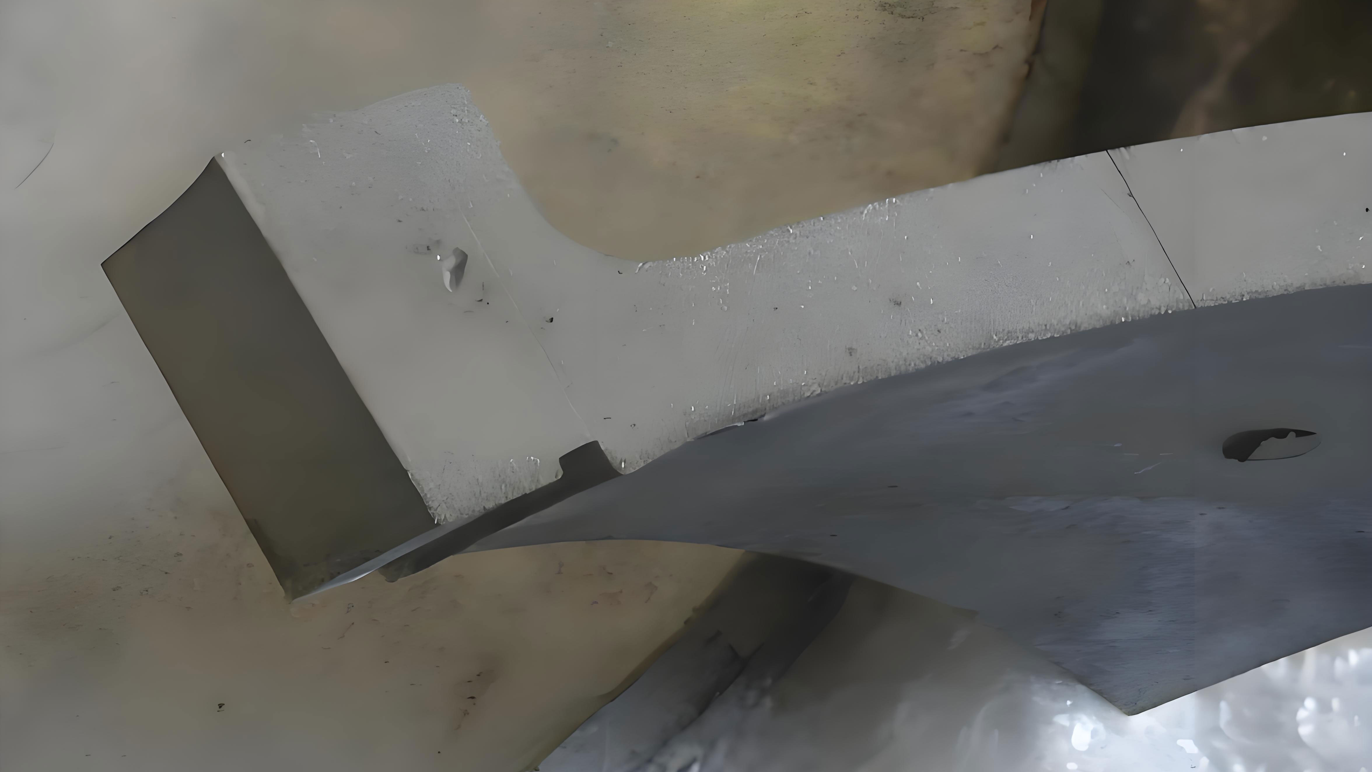
The elbow specifications were: Diameter 95 mm, Wall Thickness 7.5 mm, Material Aluminum Alloy 5052. The presence of a through-wall defect in a thick-walled component operating at -183°C was highly abnormal. Aluminum alloys for cryogenic service are chosen for their toughness; a simple manufacturing flaw like a sand hole might have been present but sealed or non-propagating under ideal conditions. This suggested an active degradation mechanism had exploited this flaw.
Investigation Findings:
- Historical Context: The unit had been in standby mode for nearly four years. During this period, the oxygen circuit was kept under a slight positive pressure (~0.1 MPa.G) using feed gas from the main oxygen pipeline network.
- Source of Contamination: The feed gas connection to the liquefier was at the lowest point of the oxygen compressor’s discharge header. It was later discovered that the compressor’s intercoolers had been leaking water into the gas stream for an extended, undetected period prior to the liquefier restart.
- Mechanism of Water Ingestion: Each time the upstream oxygen compressor started, a surge of pressure would drive accumulated free water from the header into the idle liquefier’s oxygen piping. Over years of standby, a significant amount of water, containing dissolved ions from the cooling water, migrated to and pooled in the lowest point—the very elbow where the failure occurred.
| Step | Action/Discovery | Conclusion |
|---|---|---|
| 1. Leak Localization | Pressure testing after de-insulation finds sand hole in LOX elbow. | Physical failure point identified. |
| 2. Material Assessment | Elbow is thick-walled Al5052, unsuitable for simple fatigue. | Pre-existing defect likely exacerbated. |
| 3. Contamination Trace | Free water found in valves downstream of cold box. History of compressor cooler leaks confirmed. | Pathway for corrosive agent established. |
| 4. Corrosion Analysis | Cut-out elbow internal inspection reveals calcium scale, water tracks, and localized pitting/corrosion at the bottom. | Casting hole acted as initiation site for concentrated pitting corrosion. |
Upon cutting out the suspect elbow, the internal visual inspection was conclusive. Clear water stain tracks lined the interior, and the bottom quadrant, where water had pooled, exhibited severe localized corrosion. Multiple deep pits were present, with the deepest effectively reducing the wall thickness to nearly 1 mm, with the sand hole being the final point of penetration. This was not merely a manufacturing defect but a failure caused by corrosion under stagnant conditions (CUSC), with the casting hole morphology accelerating the process.
Corrosion Mechanism: Chloride-Induced Pitting
The cooling water used in the oxygen compressor’s intercoolers typically contains various salts. Chloride ions (Cl⁻) are particularly aggressive towards aluminum alloys, even at low concentrations. The free water that entered the system was, in essence, a dilute chloride solution.
Electrochemical Corrosion Process:
- Anodic Reaction (at the pit/ casting hole site): $$ Al \rightarrow Al^{3+} + 3e^- $$
- Cathodic Reaction (on the surrounding surface): $$ O_2 + 2H_2O + 4e^- \rightarrow 4OH^- $$
Within the confined geometry of a pit or a surface-breaking casting hole, the hydrolysis of \( Al^{3+} \) ions generates \( H^+ \) ions, creating an acidic local environment:
$$ Al^{3+} + 3H_2O \rightarrow Al(OH)_3 + 3H^+ $$
This acidity further accelerates the dissolution of aluminum. Chloride ions are highly effective at breaking down the passive oxide film (\( Al_2O_3 \)) that protects aluminum and, once pitting initiates, they migrate into the pit to maintain charge neutrality, exacerbating the autocatalytic acidic cycle.
The corrosion rate is influenced by factors including chloride concentration [Cl⁻], temperature (T), and exposure time (t). An empirical relationship for pitting corrosion depth (d) can be conceptually represented as:
$$ d \propto k \cdot [Cl^-]^n \cdot f(T) \cdot t $$
where \( k \) is a material-environment constant, and \( n \) is an exponent often between 0.5 and 1. The presence of a physical discontinuity like a casting hole provides a perfect occluded site for this chemistry to establish itself, shielding it from dilution or passivation.
| Factor | Condition in this Failure | Impact on Corrosion |
|---|---|---|
| Chloride Ion Concentration | ~150 mg/L in cooling water, concentrated by evaporation. | High – Directly attacks passive layer, stabilizes pits. |
| Oxygen Availability | Limited in pooled water, but sufficient from feed gas during pressurization. | Moderate – Supports cathodic reaction. |
| Stagnancy / Flow | Completely stagnant for extended periods (~4 years). | High – Allows buildup of corrosive chemistry, prevents washing. |
| Geometric Defect (Casting Hole) | Pre-existing surface cavity. | Very High – Traps electrolyte, creates differential aeration cell, focuses attack. |
| Temperature | Ambient during standby; cryogenic during operation. | Cyclic – Corrosion occurred at ambient. Thermal cycling may have stressed the thinned wall. |
Corrective Actions and Preventive Strategies
The immediate corrective action was the replacement of the corroded elbow with a new component made from certified cryogenic-grade aluminum alloy. The new piping was subjected to stringent pressure testing, non-destructive examination (NDE), thorough purging, and a “cold shock” test (cooling with nitrogen vapor) to verify integrity before recommissioning.
To prevent recurrence, a multi-layered defense strategy was implemented, addressing both the root cause (contamination) and the enabling condition (undetected degradation).
| Category | Measure | Purpose |
|---|---|---|
| Contamination Control | Installation of online dew point analyzers with alarms on all feed gas (O₂, N₂) lines entering the liquefier cold box. | Provide continuous, early warning of moisture ingress. Critical for detecting upset conditions. |
| Enhanced inspection and leak testing protocols for all compressor coolers (oxygen, nitrogen, expander boosters). | Proactively identify and repair cooler leaks before they contaminate the process gas. | |
| Operational & Design Modifications | Revision of standby procedures for idle liquefiers. Evaluation of using dry instrument air or specially dried gas for padding instead of direct process gas from a potentially wet header. | Eliminate the pathway for introducing contamination during idle periods. |
| Consideration of installing a condensate drip leg with automatic drain in the feed gas line upstream of the cold box. | Physically remove any entrained liquid before it enters sensitive cryogenic equipment. | |
| Establishing a regular “health check” pressure test and internal inspection schedule for idle units, especially after known upsets in upstream plants. | Detect corrosion or other degradation before a catastrophic leak occurs. | |
| Material & Quality Assurance | Stressing the importance of rigorous material certification and NDE (like dye penetrant testing) for all critical cryogenic components, especially elbows and fittings, to identify potential casting holes before installation. | Eliminate inherent material defects that can become initiation sites for corrosion or fatigue. |
The thermodynamic cost of such a failure is significant. A leak in a cryogenic system not only represents a product loss but also a loss of refrigeration (exergy). The refrigeration loss \( \Delta Q_{loss} \) due to leaking cold fluid can be approximated by considering the enthalpy change of the leaked stream from its state inside the process to the warm environment:
$$ \Delta Q_{loss} = \dot{m}_{leak} \cdot (h_{leak, env} – h_{leak, process}) $$
where \( \dot{m}_{leak} \) is the leak rate. For leaking liquid oxygen at -183°C warming to 25°C, \( \Delta h \) is substantial, representing a direct drain on the system’s refrigeration capacity and thus its production efficiency.
Conclusion and Lessons Learned
The failure of the oxygen liquefier elbow was a textbook example of a multi-factor engineering failure. It was not caused by a single error, but by a sequence: a likely pre-existing material imperfection (a casting hole), combined with an operational upset (cooler leaks upstream), which introduced a corrosive environment (chloride-laden water) into a system during a vulnerable period (long-term standby). The stagnant conditions allowed localized pitting corrosion to concentrate its attack on the defect site, eventually leading to a through-wall sand hole and a dangerous cryogenic leak.
The key lessons reinforce fundamental principles in cryogenic plant management:
- Vigilance Against Contamination: Moisture and foreign substances are the enemies of cryogenic systems. Robust monitoring and strict maintenance of upstream equipment are non-negotiable.
- Understanding Failure Mechanisms: Defects like casting holes are not just manufacturing issues; they are potential focal points for accelerated corrosion or fatigue. Their significance must be evaluated in the full context of the process environment.
- Defense in Depth: Prevention requires multiple barriers: quality assurance at the component level, protective instrumentation, prudent operational procedures, and proactive inspection regimes. No single measure is sufficient.
- Investigative Rigor: When an anomaly like an unexplained temperature drop occurs, a systematic root-cause analysis that looks beyond the immediate symptom is essential. In this case, connecting the cold box leak to historical compressor issues several years prior was crucial.
This incident serves as a potent reminder that the integrity of high-integrity systems often depends on the control of seemingly mundane factors like water chemistry and standby procedures, and that material defects such as casting holes can be the weak link that transforms a controllable upset into a critical failure.