
The stability of liquid levels in separation and filtration equipment is a fundamental operational parameter in offshore production facilities. A common method for achieving this stability involves the use of an automatic control valve on a recirculation or backflow line. This valve modulates the flow of fluid returning to the vessel, counteracting inflow fluctuations. While conceptually straightforward, the practical implementation of such control loops is highly sensitive to system layout. A defective design, particularly one that promotes unfavorable fluid transients, can lead to severe and recurring mechanical damage, manifesting as pervasive pitting corrosion or erosion—often described as casting holes. I was confronted with precisely such a scenario involving a pre-filtration water tank on an offshore platform. The backflow control valve and its adjacent piping suffered from repeated leaks due to the formation of numerous casting holes, presenting a persistent safety and environmental risk. This analysis details the investigative process, the theoretical modeling of the damaging transient phenomenon, and the effective engineering solution that was implemented.
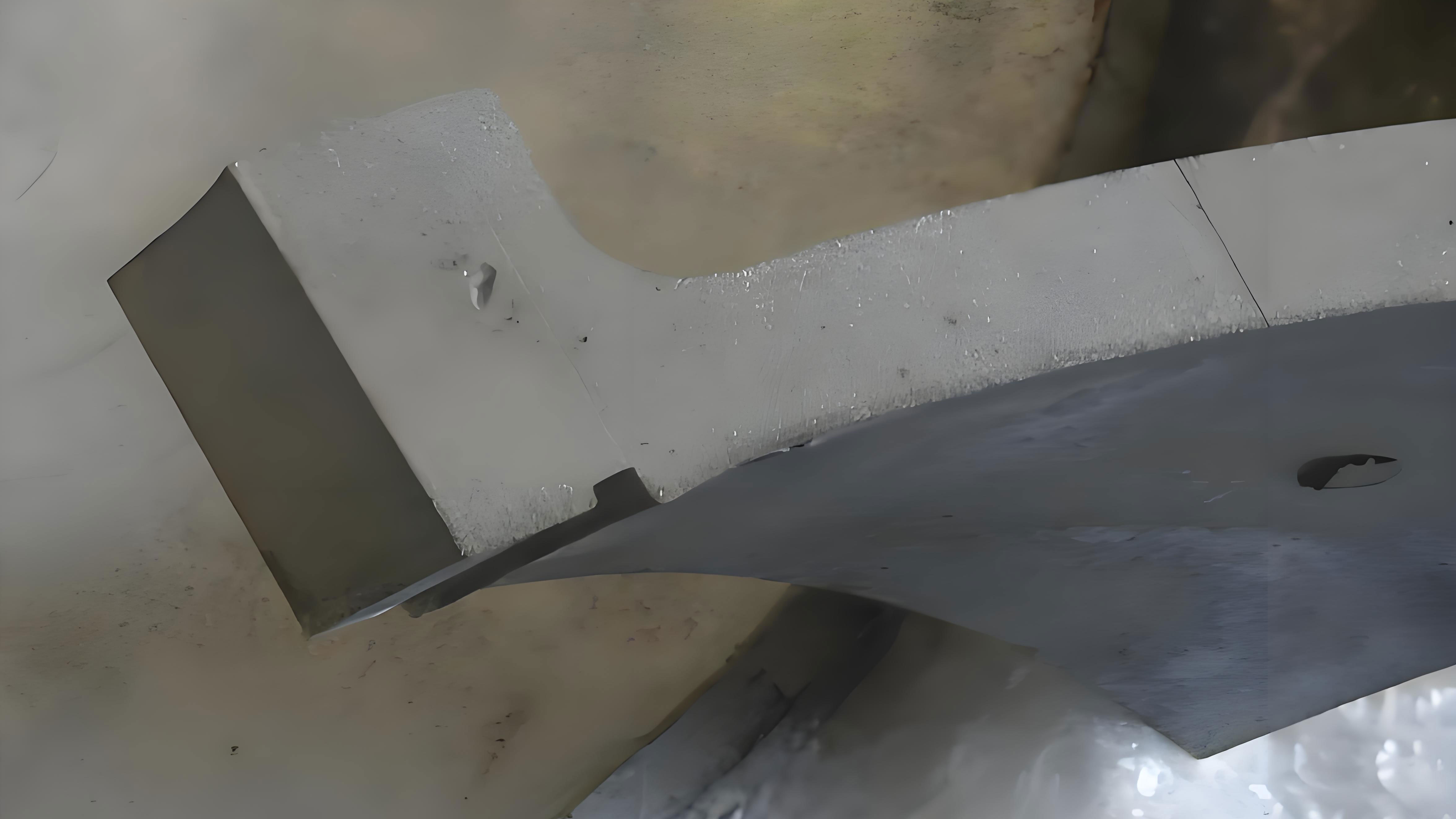
The system in question centered on a pre-filtration water tank located on the lower deck of the platform. The tank’s level was controlled by regulating the flow of water recycled from the discharge of a transfer pump back into the tank. This was accomplished by an automatic control valve (designated LV-3031) situated on a vertical pipe run approximately 3.5 meters above the tank’s top, on the mezzanine deck. The valve was programmed to adjust its position every few minutes to maintain level, with each actuation cycle lasting about 3 seconds. Within a year of operation, the pipeline downstream of this control valve began to develop leaks. Initial repairs by welding were unsuccessful, as the leaks recurred frequently. The problem escalated when the valve body itself failed, showing severe damage. Replacement of the valve and a section of the downstream pipe provided only a temporary reprieve; the new components began developing casting holes within months, necessitating over ten repair welds in a two-year period. Inspection of the removed pipe section revealed a shocking condition: the interior surface was densely covered with pits and perforations of varying sizes, a clear sign of aggressive, localized damage mechanism rather than general corrosion. This recurring failure pattern signaled a fundamental flaw in the system’s dynamics.
The initial suspicion fell on water hammer pressure surges caused by the rapid closure of the control valve. To assess this, a simplified model of direct water hammer was analyzed. The Joukowsky equation gives the theoretical pressure rise ΔP from an instantaneous stoppage of flow:
$$ \Delta P = \rho a \Delta v $$
Where ρ is the fluid density, a is the speed of the pressure wave, and Δv is the change in fluid velocity. The wave speed a depends on the fluid and pipe properties:
$$ a = \frac{\sqrt{K/\rho}}{\sqrt{1 + \frac{K D}{E e}}} $$
Here, K is the bulk modulus of the fluid, E is Young’s modulus for the pipe material, D is the pipe internal diameter, and e is the pipe wall thickness. Using system parameters (ρ ≈ 1025 kg/m³, K = 2.0e9 Pa, E = 1.96e11 Pa, D = 0.15 m, e = 0.0045 m), the wave speed a was calculated to be approximately 1206 m/s. For a typical flow velocity v of 3 m/s, an instantaneous closure would yield ΔP ≈ 3.7 MPa. However, the valve closure was not instantaneous; it took about 3 seconds (tc). The critical time for direct water hammer is the pipe period, T = 2L / a, where L is the length from the valve to the nearest reflection point (a pipe elbow or the tank). With L ≈ 1.05 m, T ≈ 0.0017 s. Since tc >> T, the condition was that of an indirect water hammer, where the pressure surge is significantly attenuated by wave reflections. A simplified estimation for indirect water hammer pressure is:
$$ \Delta P_{indirect} = \rho a \Delta v \frac{T}{t_c} $$
This calculation yielded a negligible pressure surge of only about 2.1 kPa. Given that the normal operating pressure in the line was around 500 kPa, the stress from water hammer during valve closure was conclusively ruled out as the primary cause of the severe casting holes. This finding was corroborated by the fact that the most severe damage was observed downstream of the valve, not upstream where closure-induced water hammer effects are strongest.
Attention then shifted to the valve opening phase. The system geometry was key: the control valve was at a high point, with a short, downward-sloping pipe segment connecting it back to the tank. When the valve was closed, this downstream pipe segment would naturally drain, leaving it largely empty or filled with a trapped air pocket (a滞留气团). Upon valve opening, the full-pressure flow from the pump would rush into this empty space, violently impacting and compressing the trapped air pocket. This phenomenon, known as “flow-induced transient due to an entrapped air pocket,” generates extreme pressure pulses. To quantitatively analyze this, a rigid water column model was adopted, assuming incompressible water and a rigid pipe wall, with the air pocket behaving as an ideal gas. The system at time t after valve opening is defined by the following key variables and equations.
| Variable | Description |
|---|---|
| La(t) | Length of the trapped air pocket in the pipe. |
| Ha(t) | Absolute pressure head of the air pocket (in meters of water). |
| U(t) | Velocity of the water column entering the pipe. |
| Lx(t) | Length of the water-filled section of the previously empty pipe. |
The governing equations are:
1. Gas State Equation (Polytropic Compression):
$$ H_a(t) \cdot [L_a(t)]^m = H_{a0} \cdot [L_{a0}]^m = constant $$
Where m is the polytropic index (taken as 1.4 for adiabatic compression), and Ha0, La0 are initial conditions.
2. Continuity at the Air-Water Interface:
$$ \frac{dL_a}{dt} = -U(t) $$
This states that the rate of decrease of the air pocket length equals the water velocity.
3. Motion Equation for the Water Column (Applying Newton’s Second Law):
The driving force is the difference between the supply pressure head (Hu) and the air pocket pressure head (Ha), minus friction and minor losses. For the water column of instantaneous length Lx(t):
$$ \frac{L_x(t)}{g} \frac{dU}{dt} = H_u – H_a(t) – \Delta Z – \left( \frac{f L_x(t)}{D} + \sum \epsilon_j + \epsilon_v(t) \right) \frac{U|U|}{2g} $$
Where:
– g is gravity.
– ΔZ is the elevation difference.
– f is the Darcy friction factor.
– ∑εj represents minor loss coefficients in the filled section.
– εv(t) is the time-varying loss coefficient of the opening control valve.
The relationship Lx(t) = Lfixed + (La0 – La(t)) connects the water column length to the air pocket length. This system of differential-algebraic equations was solved numerically using the fourth-order Runge-Kutta method. The initial conditions were U=0 and La = La0 (the length of the empty pipe section) at t=0. The valve opening was modeled as linear over 3 seconds.
Using system parameters (Hu ≈ 51 m, La0 ≈ 1.05 m, D=0.15 m, f=0.02), the simulation predicted extreme transient pressures. The absolute pressure head of the air pocket, Ha(t), spiked to values exceeding 90 meters of water column during the initial milliseconds of the valve opening. This translates to a peak transient pressure Ppeak:
$$ P_{peak} = \rho g H_a \approx 1025 \times 9.81 \times 92.67 \approx 0.93 \text{ MPa (absolute)} $$
This represents a pressure surge nearly double the normal operating pressure, occurring as a sharp impulse each time the valve opened. Furthermore, the violent rush of water into an irregular space (the valve cavity and pipe) causes rapid acceleration and deceleration, leading to localized pressure drops below the vapor pressure of the water. This results in the formation of vapor cavities or bubbles (cavitation). When these bubbles are subsequently transported into regions of higher pressure, they collapse implosively. The collapse of these cavitation bubbles is immensely destructive; micro-jets and shock waves generated during collapse can create instantaneous local pressures on the metal surface exceeding 1000 MPa. This process, repeated millions of times over thousands of valve cycles, leads to classic cavitation erosion. The material loss manifests as a porous, sponge-like surface covered in deep, isolated pits—exactly matching the observed “casting holes” on the valve body and downstream pipe. The combined mechanism of high-pressure air pocket hammer and cavitation bubble collapse provided a complete explanation for the failure.
The root cause was therefore unequivocally linked to the system layout that allowed the downstream pipe to drain and trap air. The solution required eliminating the condition for air pocket formation during valve closure. The proposed and implemented modification was a simple yet effective re-routing of the downstream piping. The pipe was reconfigured into an inverted “U” shape (a gooseneck), with the crest of the U positioned above the control valve elevation. This ensured that whenever the control valve closed, the vertical leg of the U on the valve’s downstream side would remain full of water, creating a permanent liquid seal. Upon valve opening, the water column would move in a controlled manner, pushing the existing water ahead of it instead of slamming into a compressible air pocket. This redesign eliminated both the large pressure transients from air compression and the conditions for severe cavitation.
| Aspect | Original Design | Modified Design |
|---|---|---|
| Downstream Condition (Valve Closed) | Empty pipe, trapped air pocket. | Pipe full of water, no air pocket. |
| Transient on Valve Opening | Violent water hammer & cavitation. Peak pressure ~0.93 MPa. | Smooth water column movement. Negligible transient. |
| Primary Damage Mechanism | Cavitation erosion & air pocket shock, leading to casting holes. | Eliminated. |
| Maintenance Impact | Frequent failures, repairs every few months. | No failures post-modification. |
The effectiveness of this intervention has been proven over an extended operational period. Following the modification, no further leaks or casting holes have developed in the previously problematic section. Ultrasonic thickness measurements conducted months later confirmed no further wall thinning. This successful resolution translated into significant benefits:
- Eliminated Safety & Environmental Hazard: The risk of uncontrolled produced water release was removed.
- Cost Savings: Estimated annual savings of $15,000 in repair materials, contractor costs, and production downtime.
- Reduced Workload: Elimination of over 100 man-hours per year dedicated to emergency repairs and welding.
- Improved Reliability: The system now operates as intended, with the control valve performing its level regulation function without self-destructing.
In conclusion, the recurring formation of casting holes in this backflow pipeline system was a direct consequence of a design-induced transient flow phenomenon. Theoretical modeling, beginning with the dismissal of closure-induced water hammer and culminating in a detailed analysis of the opening transient involving an entrapped air pocket, pinpointed the cause as a combination of high-pressure shock and cavitation erosion. The pressure surge calculated from the rigid model, approaching 0.93 MPa, provided a quantitative basis for the observed damage. The implemented solution, an inverted U-pipe modification, was a targeted and elegant engineering fix that addressed the root cause by preventing air entrapment. This case underscores the critical importance of considering transient hydraulic phenomena in the design of process piping systems, especially those involving automatic valves and elevated pipe sections, to prevent costly and hazardous failures like pervasive casting holes.