
In my extensive experience within foundry operations, addressing internal defects remains one of the most persistent challenges. Among these, porosity in casting stands out as a primary culprit for scrapped components, particularly those requiring pressure tightness. The journey from a problematic casting process to a reliable one offers profound insights into the fundamental principles of metalcasting. I will delve into a detailed case study concerning an aluminum alloy shell casting, systematically breaking down the root causes of gas-related defects and the step-by-step methodological improvements that led to their virtual elimination. This narrative will serve as a framework to explore the broader scientific and engineering principles governing porosity in casting.
Introduction to the Casting and Its Critical Requirement
The component in question was a structural shell made from aluminum alloy ZL114A (equivalent to A357.0), a common choice for high-integrity applications due to its good castability and mechanical properties. The casting had complex three-dimensional geometry with an average wall thickness of approximately 5 mm and a final weight of about 1.5 kg. The paramount quality requirement was pressure tightness: the internal cavity had to withstand a pneumatic pressure test of 0.5 MPa for a duration of 15 seconds without any trace of gas leakage. This is a stringent test that mercilessly reveals any interconnected porosity in casting networks beneath the surface. The initial production process utilized green sand molding and cores.
Deconstructing the Initial Process: A Recipe for Porosity
The original foundry practice, while seemingly straightforward, incorporated several elements that collectively guaranteed the formation of porosity in casting. The initial process parameters are summarized below:
| Process Parameter | Initial Design Specification |
|---|---|
| Molding Media | Clay-bonded sand (GFN 70-100) for both mold and core. |
| Parting Line / Orientation | Base plate facing up (cope), sloped side walls facing down (drag). |
| Gating System Type | Top-gating. |
| Gating Ratio (Sprue:Runner:Ingate) | 1 : 2 : 2.2 |
| Ingate Cross-Sectional Area | Approx. 4.5 cm² |
| Feeding System | Two cylindrical risers (Ø50 mm x H50 mm) on the top (base) face. |
| Pouring Temperature | 740°C |
| Pouring Time | 10 seconds |
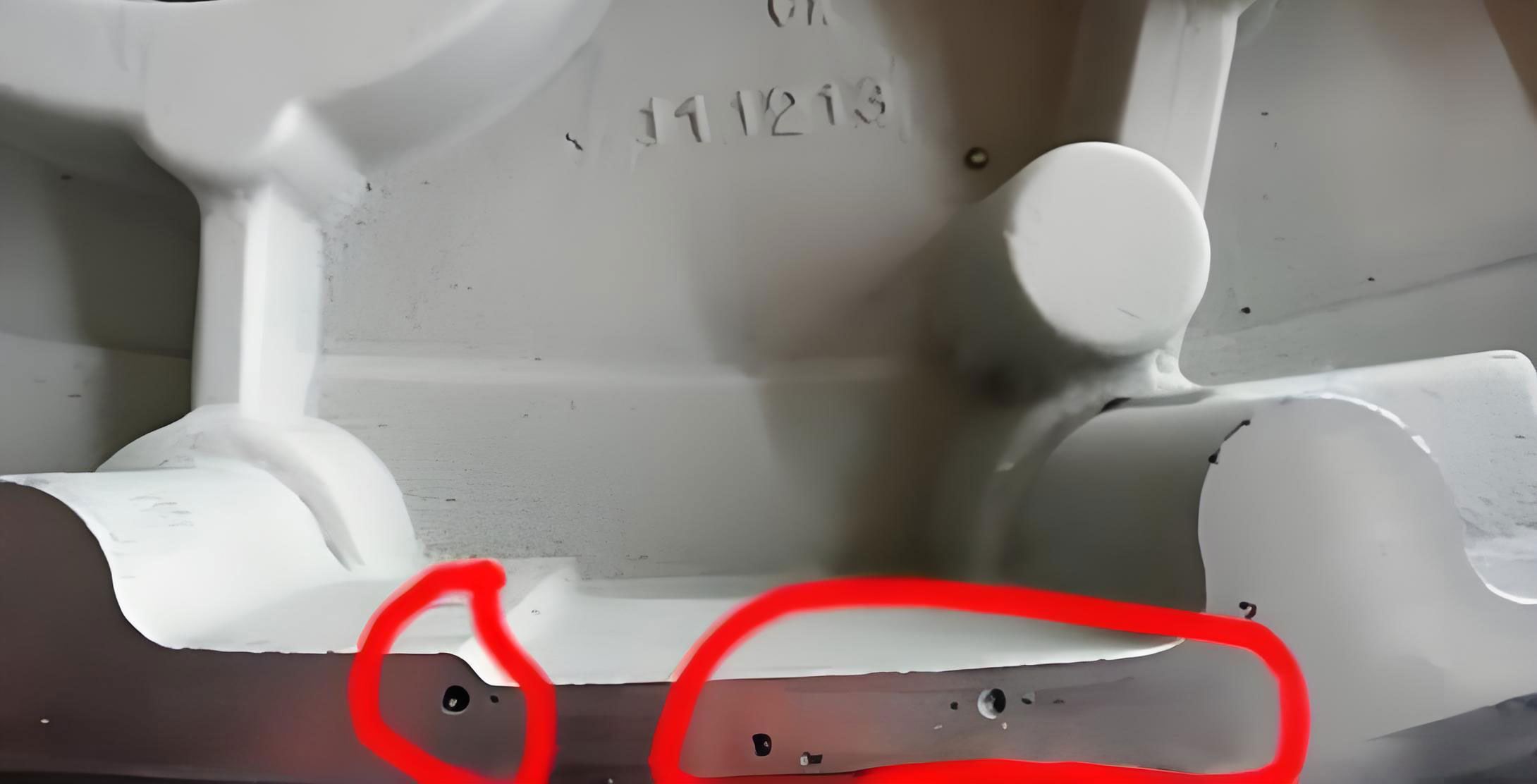
The outcome of this initial process was a casting with acceptable surface finish but a catastrophic failure rate in the pressure test—nearly 90% of castings leaked. The leakage points were predominantly located on the sloped side walls. Fracture analysis revealed the presence of gas pores with diameters ranging from 0.5 to 1 mm. This clear failure prompted a root-cause analysis, which identified three synergistic factors contributing to the severe porosity in casting.
1. Turbulent Filling and Air Entrainment
The top-gating system caused molten metal to fall freely into the mold cavity. This fall generates significant turbulence, which fragments the metal stream and traps mold atmosphere and air from the pouring basin within the liquid. The Reynolds number ($Re$), which indicates flow regime, can be conceptually applied here (though simplified for molten metal flow):
$$Re = \frac{\rho v D}{\mu}$$
where $\rho$ is density, $v$ is velocity, $D$ is hydraulic diameter, and $\mu$ is dynamic viscosity. The high velocity ($v$) from the vertical drop leads to a very high $Re$, signifying turbulent flow. Turbulence is a primary driver for air entrainment, a direct source of porosity in casting.
2. Inadequate Core Venting and Gas Generation
The core was made solid with clay sand, reinforced with internal rods for strength. When surrounded by the hot metal, the moisture and organic compounds in the clay binder undergo rapid decomposition, generating large volumes of gas (predominantly steam, CO, CO₂, and hydrocarbons). The equation for water vapor generation is a key contributor:
$$ \text{Clay-H}_2\text{O} + \text{Heat} \rightarrow \text{Steam} (H_2O_{(g)}) $$
With no designed escape path, the gas pressure inside the core builds up until it exceeds the metallostatic pressure at the metal-core interface. The gas then infiltrates the solidifying metal, creating subsurface blowholes and pinholes. This is a classic case of core-gas porosity in casting.
3. Poor Feeding and Shrinkage Porosity Interaction
The two risers were placed on the thick, flat base plate. While they effectively fed this region, they provided negligible feeding to the more distant sloped side walls. During solidification, these areas developed isolated liquid pockets. As these pockets solidified and shrank, they required liquid metal supplementation. The inadequate feeding led to the formation of interdendritic shrinkage cavities. Often, entrapped gas from the turbulent fill migrates to and coalesces within these shrinkage zones, creating larger, interconnected defects. Thus, the observed leakage was likely a combination of true gas pores and shrinkage-gas complexes, all falling under the umbrella of detrimental porosity in casting.
A Systematic, Multi-Pronged Improvement Strategy
Addressing the problem required a holistic redesign targeting each identified root cause. The revised process was a complete overhaul, as detailed in the following table.
| Process Parameter | Improved Design Specification | Rationale & Targeted Defect Mechanism |
|---|---|---|
| Molding Media | Mold: Clay sand (unchanged). Core: Resin-bonded sand (finer, GFN 50-120) with a central Ø30 mm vent hole. | Finer sand provides better surface finish. Resin sand generates less moisture-related gas. The vent hole provides a direct, low-resistance escape path for core gases, preventing their invasion into the metal. |
| Parting Line / Orientation | Inverted: Base plate facing down (drag), sloped side walls facing up (cope). | Places the critical, leak-prone side walls in the upper portion of the mold, making them easier to feed via risers and allowing buoyant gases to rise away from them. |
| Gating System Type | Bottom-gating. | Promotes laminar, non-turbulent fill. Metal rises steadily in the cavity, allowing air and mold gases to be displaced upward ahead of the liquid front and out through vents/risers. |
| Gating Ratio | 1 : 2 : 2.5 | Maintains a pressurized system to minimize air aspiration. The increased ingate area relative to sprue base helps reduce initial entry velocity. |
| Ingate Design | Two ingates with a total area of ~5.2 cm², placed at the bottom of the cavity. | Introduces metal at the lowest point for calm, upward filling. |
| Feeding System | One elongated riser positioned along the top edge of the sloped side wall. | Places the feeder directly atop the thermally “hot spot” of the critical wall section, providing effective directional solidification and liquid feed to compensate for shrinkage. |
| Pouring Temperature | 710°C | Lower temperature reduces total gas solubility in the liquid aluminum and shrinkage volume, while still maintaining fluidity. |
| Pouring Time | 8 seconds | Slightly faster pour (due to larger ingates) maintains thermal gradient but is non-turbulent due to bottom entry. |
The Science Behind the Solutions: An In-Depth Look
The Critical Role of Gating Design in Porosity Prevention
The shift from top to bottom gating is arguably the most impactful change for reducing air entrainment porosity in casting. The velocity of the metal as it enters the cavity ($v_{entry}$) is governed by Bernoulli’s principle and the effective head height. For a bottom-gated system where the metal head rises during filling, the instantaneous velocity decreases over time. A simplified model for the initial fill velocity from a sprue is:
$$ v = \sqrt{2gh} $$
where $g$ is gravity and $h$ is the effective metallostatic head. By introducing the metal at the bottom, we minimize the damaging impact of this velocity by directing it horizontally along the bottom of the mold rather than vertically into a liquid pool. The goal is to keep the flow within the laminar or transitional regime to prevent air bubble entrapment. The improved fill pattern drastically reduces the initial quantity of air introduced, which is the first line of defense against porosity in casting.
Core Venting and Gas Dynamics
The creation of an explicit vent in the core addresses the gas generation problem at its source. The pressure build-up inside an unvented core ($P_{core}$) can be modeled as a function of gas generation rate ($\dot{G}$), permeability of the core sand ($k$), and venting area ($A_v$). Darcy’s law for flow through a porous medium is relevant for the sand itself, but the vent hole provides a much higher permeability path. The key principle is to ensure that the total flow resistance for the generated gas to escape to the atmosphere is lower than the resistance for it to penetrate the liquid metal. The pressure required for metal penetration ($P_{penetration}$) is given by:
$$ P_{penetration} = \rho_m g h_m + \frac{2\gamma \cos\theta}{r} $$
where $\rho_m g h_m$ is the metallostatic pressure, $\gamma$ is the surface tension, $\theta$ is the contact angle, and $r$ is the pore radius at the metal-core interface. By providing a large vent, we keep $P_{core}$ near atmospheric pressure, ensuring it remains below $P_{penetration}$, thereby preventing gas invasion and the consequent sub-surface porosity in casting.
Solidification Feeding and the Niyama Criterion
The relocation and redesign of the riser were crucial for mitigating shrinkage-related porosity in casting. Effective feeding requires creating a directional solidification gradient toward the riser. The thermal gradient ($G$) and solidification rate ($v_s$) are key parameters. A useful criterion for predicting the likelihood of shrinkage porosity in casting is the Niyama criterion ($N_y$):
$$ N_y = \frac{G}{\sqrt{v_s}} $$
Areas with a Niyama value below a critical threshold are prone to shrinkage porosity. By placing the riser directly on the hot spot of the sloped wall, we maximize $G$ in that region, thereby increasing $N_y$ above the critical level and ensuring sound metal. Furthermore, the lower pouring temperature reduces the total solidification shrinkage volume ($\Delta V$), which can be approximated as:
$$ \Delta V = V_0 \cdot (\beta_s + \beta_l \cdot f_l) $$
where $V_0$ is initial volume, $\beta_s$ is solidification shrinkage coefficient, $\beta_l$ is thermal contraction coefficient of the liquid, and $f_l$ is the liquid fraction. A lower start temperature reduces the $f_l$ term, lessening the demand on the riser.
Results and Validation: From Theory to Production
The implementation of the multi-faceted improved process yielded transformative results. The yield (casting weight vs. total poured weight) improved slightly. Most critically, the pressure test failure rate plummeted from 90% to approximately 2%. This dramatic improvement validated the root-cause analysis and the synergistic effectiveness of the changes. The remaining 2% of defects can be attributed to normal process variability, which can be further controlled through statistical process control (SPC) on parameters like sand properties, binder ratios, and metal quality (e.g., hydrogen content).
The success of this project underscores that porosity in casting is seldom caused by a single factor. It is typically the result of a chain of events: turbulent filling introduces gas, inadequate venting adds more gas, and poor feeding creates preferred sites for this gas to accumulate and expand during solidification. A systemic view is essential for effective mitigation.
Expanding the Discussion: General Principles for Porosity Mitigation in Aluminum Castings
Building on this case study, I can generalize key principles applicable to a wide range of aluminum casting operations aiming to minimize porosity in casting.
| Defect Cause Category | Specific Mechanisms | Generalized Prevention Strategies |
|---|---|---|
| Entrapped Air & Mold Gas | Turbulent filling, poor mold/core venting, high sand moisture/binder content. | Use bottom, side, or stepped gating. Maximize venting area in molds and cores (vents, permeable plugs, venting channels). Optimize sand properties to reduce gas generation. Apply mold/coatings with low gas evolution. |
| Gas Solubility (Hydrogen) | Hydrogen pickup from moisture in charge materials, atmosphere, or refractories. Decreased solubility upon solidification leads to gas precipitation. | Implement rigorous melt degassing (rotary impeller with inert gas, lance purging). Keep charge materials clean and dry. Use a protective melt cover. Conduct Reduced Pressure Test (RPT) for hydrogen monitoring. The solubility drop is described by Sieverts’ Law: $[H] = K_H \sqrt{P_{H_2}}$, where $[H]$ is dissolved hydrogen concentration and $P_{H_2}$ is the partial pressure of hydrogen. |
| Shrinkage Porosity | Lack of liquid feed during solidification due to unfavorable thermal gradients or insufficient feeding volume/pressure. | Design rigging for directional solidification using Chvorinov’s Rule ($t_s = B \cdot (V/A)^n$) to identify thermal centers. Use adequate, properly sized risers or feeder heads. Consider chilling to control solidification sequence. Apply feeder aids (exothermic/insulating sleeves). |
| Interaction Porosity | Entrapped gas bubbles migrating to and being stabilized by shrinkage cavities (the most common scenario). | Attack the problem from both fronts: minimize gas sources and optimize feeding. This combined approach is often the only way to achieve high-integrity, leak-tight castings. |
A quantitative approach to process design is invaluable. For instance, calculating the theoretical volume of gas generated from a core can inform vent sizing. Similarly, solidification simulation software is now an indispensable tool for predicting hot spots and optimizing riser placement before any metal is poured, allowing for proactive mitigation of porosity in casting.
Conclusion: A Foundational Philosophy for Casting Integrity
The journey to eliminate porosity in casting in this aluminum shell component reinforces a foundational philosophy in metal casting: soundness is engineered, not incidental. It requires a deliberate and interconnected approach to fluid dynamics, heat transfer, and materials science. The three pillars of this philosophy are Control (of melt cleanliness and process variables), Calm (filling to prevent air entrapment), and Chill (or more broadly, controlled solidification to enable feeding).
By first conducting a disciplined root-cause analysis to distinguish between gas entrapment, gas evolution, and shrinkage mechanisms, and then implementing targeted, scientifically-backed countermeasures—such as bottom gating, aggressive core venting, and thermodynamically sound riser design—the pervasive challenge of porosity in casting can be overcome. The transition from a 90% failure rate to a 98% success rate is a testament to the power of applying fundamental principles to practical foundry problems. This case serves as a robust template for diagnosing and solving integrity issues across a wide spectrum of cast aluminum components, ensuring they meet the most demanding structural and pressure-tightness requirements.