
In my experience within the foundry industry, addressing defects in critical components like cylinder heads is paramount for ensuring product quality and operational efficiency. One of the most persistent and challenging issues encountered is the formation of gas porosity in castings. This article delves into a comprehensive analysis of porosity in casting for cylinder heads produced via a vertical pouring process with fully assembled cores, and details the systematic process optimizations undertaken to mitigate this defect. The initial scrap rate due to porosity in casting was alarmingly high, exceeding 22%, which necessitated a thorough investigation and multi-faceted intervention.
The cylinder head in question is a complex alloy gray iron component, with approximate dimensions of 540 mm x 240 mm x 120 mm and a weight of 45 kg. Its design incorporates a double-layer water jacket structure, featuring thin internal partitions with a wall thickness of 5±0.5 mm. This complexity inherently increases the risk of cold shuts and shrinkage porosity. Furthermore, the component must pass 100% pressure tightness tests for both water and oil passages, leaving no room for internal defects like sand burning or, most critically, porosity in casting. The transition from a traditional horizontal flask molding with hot-box cores to a fully integrated cold-box core assembly and vertical pouring process was aimed at resolving issues like cold shuts and sand adhesion. However, this advanced process initially introduced a severe challenge in the form of subsurface blowholes, primarily concentrated on the intake side (the top during pouring), significantly impacting yield.
The established vertical casting process utilizes cold-box resin-bonded cores assembled into a complete package, which is then placed into green sand molds for upper and lower drags. The gating system is a bottom-fed, partially choked design intended to ensure smooth filling and slag trapping. Despite these design intentions, preliminary production runs were plagued by defects. A root-cause analysis was conducted, focusing on the entire production chain from core making to molding and pouring. The key observed issues were: visible smoke emanating from cores after microwave drying, mold wall movement or “boil” during metal pouring, and shrinkage-related problems in the castings. A cause-and-effect analysis pinpointed several interrelated factors contributing to porosity in casting:
- Core Gas Generation: Incomplete curing or excessive residual solvents in cold-box cores can lead to high gas evolution during metal pouring.
- Inadequate Venting: Insufficient pathways for the escape of gases generated from the cores and the mold coating.
- Coating Performance: The permeability and gas-shielding properties of the refractory coating applied to cores significantly influence gas entrapment.
To quantify the relationship between process variables and defect formation, we can consider the fundamental equation for gas pressure buildup in a mold cavity, which is a direct driver for porosity in casting:
$$ P_g = \frac{n_g R T}{V_c} – \frac{\sigma \cos \theta}{r} $$
Where $P_g$ is the gas pressure, $n_g$ is the moles of gas generated, $R$ is the universal gas constant, $T$ is the temperature, $V_c$ is the cavity volume, $\sigma$ is the surface tension of the metal, $\theta$ is the contact angle, and $r$ is the pore radius. Our goal was to minimize $n_g$ and provide easy escape routes to prevent $P_g$ from exceeding the metallostatic pressure.
Process Optimization and Experimental Verification
1. Optimization of Core Microwave Drying Parameters
The first intervention targeted the core drying process. Cores require microwave drying to achieve sufficient strength and reduce moisture before coating. The initial parameters led to cores that were overly hot and still “smoking,” indicating residual volatiles. An orthogonal experiment was designed to adjust two key variables: microwave exposure time and the number of active magnetrons. The objective was to find a parameter set that minimized core temperature while maintaining adequate bonding strength, thereby reducing the potential gas load contributing to porosity in casting.
The experimental matrix and results are summarized in the table below. The core surface temperature was measured immediately after microwave treatment, and the coating thickness was verified after dip coating.
| Experiment # | Microwave Time (s) | Active Magnetrons | Average Core Temp. (°C) | Wet Coating Thickness (mm) | Core Integrity Post-Coating |
|---|---|---|---|---|---|
| 1 (Original) | 180 | 8 | 95 | 0.25-0.30 | Good |
| 2 | 180 | 6 | 85 | 0.28-0.33 | Good |
| 3 | 180 | 4 | 78 | 0.30-0.35 | Good |
| 4 | 150 | 8 | 82 | 0.26-0.31 | Good |
| 5 | 150 | 6 | 75 | 0.29-0.34 | Good |
| 6 | 150 | 4 | 70 | 0.32-0.36 | Good |
| 7 | 120 | 8 | 72 | 0.30-0.35 | Good |
| 8 | 120 | 6 | 68 | 0.31-0.36 | Water jacket core drop |
| 9 | 120 | 4 | 65 | 0.33-0.38 | Fair (weak bonding) |
The data shows a clear correlation: reducing both time and magnetron count lowers core temperature. However, excessive reduction (Experiment #8 and #9) compromised core strength, leading to handling issues during coating. Experiment #7 emerged as the optimal compromise, reducing the core temperature from 95°C to 72°C while maintaining structural integrity and achieving a consistent, uniform wet coating thickness of 0.30-0.35 mm. This reduction in initial core temperature directly decreased the volatile content available for gas generation during pouring, attacking one root cause of porosity in casting.
2. Enhancement of the Mold and Casting Venting Systems
Venting is arguably the most critical factor in preventing porosity in casting. The initial mold design incorporated only three vent pins in the external mold (cope and drag) to facilitate gas escape from the core package. Analysis suggested this was insufficient. The total venting area from the mold needs to be proportionally larger than the choke area of the gating system to allow gases to escape faster than molten metal fills the cavity. The original design had a vent area ratio of approximately:
$$ R_{vent\_original} = \frac{A_{vent\_mold}}{A_{choke}} \approx 0.73 $$
Where $A_{vent\_mold}$ is the total cross-sectional area of the vent pins in the mold, and $A_{choke}$ is the area of the gating system’s choke. A recommended ratio for such dense core assemblies is often greater than 1.2. Therefore, the venting system was modified in two stages:
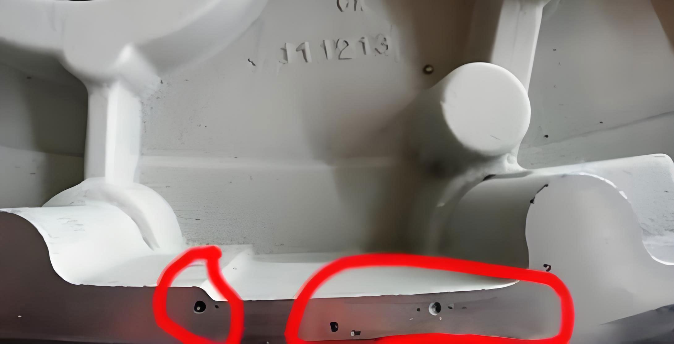
a) Mold Venting Enhancement: Five additional vent pins were added to the external mold boxes, strategically placed near the upper regions of the core assembly where gases would accumulate. This increased the mold’s venting capacity significantly.
b) Casting (In-Core) Venting Enhancement: To further guide gases out from the deepest parts of the core assembly, vent channels were incorporated directly into the core prints and core surfaces. This involved adding vent pins and thin vent strips on the core forming surfaces. Furthermore, small reservoirs were added at the roots of these vents to prevent early metal sealing. The total effective vent area from the combined system (mold vents + in-core vents) was redesigned to meet the target:
$$ R_{vent\_new} = \frac{A_{vent\_mold} + A_{vent\_core}}{A_{choke}} \geq 1.2 $$
This comprehensive approach ensured a low-resistance path for gases generated from both the sand cores and the decomposing coating, directly mitigating the pressure buildup that leads to porosity in casting.
3. Optimization of the Refractory Coating
The coating applied to cores serves as a barrier against metal penetration and sand burning, but its gas evolution characteristics are crucial. A coating with high or ill-timed gas evolution can itself become a source of porosity in casting. The original coating (denoted as Coating 1#) was suspected of having poor shielding properties and a high gas evolution rate. We evaluated two alternative coatings from the existing inventory: a general-purpose coating (Coating 2#) and a specialized anti-penetration coating (Coating 3#).
The gas evolution behavior was analyzed using a dedicated instrument, measuring the volume of gas released as a function of temperature, simulating the conditions during metal pouring. The results are presented in the table and formula below. The critical metric is the total gas evolved up to the temperature where the metal front solidifies a skin, typically around 1200°C for gray iron.
| Coating ID | Type | Gas Evolution at 1000°C (ml/g) | Gas Evolution at 1200°C (ml/g) | Peak Evolution Temperature (°C) | Permeability Number |
|---|---|---|---|---|---|
| 1# (Original) | Standard Zircon-based | 45 | 68 | 950 | ~15 |
| 2# | General Graphite-based | 32 | 48 | 1050 | ~25 |
| 3# | Special Anti-penetration | 28 | 40 | 1100 | ~30 |
The gas evolution curve can be modeled approximately by an exponential decay function for the generation rate:
$$ \frac{dV}{dT} = V_0 \cdot k \cdot e^{-k(T – T_0)} $$
Where $dV/dT$ is the gas evolution rate per degree, $V_0$ is a pre-exponential factor related to binder content, $k$ is a temperature-dependent constant, and $T_0$ is a reference temperature. Coating 3# exhibited a lower $V_0$ and a delayed peak evolution (higher $T_0$), meaning it released gas more slowly and at a higher temperature, allowing more time for venting before the metal skin formed.
Production trials with the three coatings confirmed the laboratory analysis. The scrap rate due to porosity in casting was highest with Coating 1#, significantly lower with Coating 2#, and lowest with Coating 3#. Furthermore, dissection of castings revealed superior surface finish and complete absence of metal penetration with Coating 3#. Consequently, Coating 3# was adopted as the standard. Its higher permeability and controlled gas release created a more favorable interface for gas escape, directly reducing the incidence of porosity in casting.
Integrated Results and Discussion
The individual optimizations—microwave parameter adjustment, venting system overhaul, and coating change—were implemented in a synergistic manner. The combined effect was dramatic. To quantify the improvement, we can define a Porosity Risk Index (PRI) that consolidates the key factors:
$$ PRI = \alpha \cdot \left(\frac{T_{core}}{T_{ref}}\right) + \beta \cdot \left(\frac{A_{choke}}{A_{vent\_total}}\right) + \gamma \cdot \left(\frac{V_{gas\_coating}}{V_{ref}}\right) $$
Where $\alpha$, $\beta$, $\gamma$ are weighting factors, $T_{core}$ is core temperature post-drying, $A_{vent\_total}$ is the total vent area, $V_{gas\_coating}$ is the gas evolution volume from the coating at 1200°C, and $T_{ref}$, $V_{ref}$ are reference values. The optimizations reduced each term in the equation.
The table below summarizes the key performance indicators before and after the full process optimization.
| Process Parameter | Initial State | Optimized State | % Change | Impact on Porosity in Casting |
|---|---|---|---|---|
| Core Temp. Post-Microwave (°C) | 95 | 72 | -24.2% | Reduced core gas generation |
| Mold Vent Area Ratio ($R_{vent}$) | 0.73 | 1.25 | +71.2% | Enhanced gas escape capacity |
| Coating Gas Evolution at 1200°C (ml/g) | 68 | 40 | -41.2% | Reduced gas load from interface |
| Observed Mold Boil / Smoke | Severe | Minimal | – | Visual confirmation of control |
| Scrap Rate due to Porosity in Casting | 22.69% | 1.62% | -92.9% | Primary Objective Achieved |
The results unequivocally demonstrate the effectiveness of the holistic approach. The scrap rate attributed to porosity in casting plummeted from 22.69% to 1.62%, representing a 93% reduction. This was not the result of a single “magic bullet” but a systematic engineering effort addressing each contributor to gas defect formation: the source (core temperature, coating), the path (venting), and the timing (coating gas evolution profile). The problem of porosity in casting, which was the major bottleneck in the new vertical casting process, was successfully brought under control.
Conclusion
Through detailed root-cause analysis and structured experimental verification, the critical factors leading to severe porosity in casting for a complex cylinder head produced via a vertical core assembly process were identified and remedied. The optimization strategy encompassed three pillars: 1) Minimizing initial gas potential by reducing core temperature through tailored microwave drying parameters, 2) Maximizing gas escape efficiency by radically increasing the venting area both in the mold and within the core assembly itself to exceed theoretical thresholds, and 3) Selecting a refractory coating with favorable low and delayed gas evolution characteristics coupled with high permeability. The synergistic implementation of these measures transformed a process with an unsustainable defect rate into a robust and reliable production method. This case underscores that combating porosity in casting, especially in intricate castings with dense core packages, requires a multi-variable optimization approach focused on gas generation, transport, and elimination. The principles and methodologies applied here—systematic analysis, parameter quantification via experiments, and geometric redesign based on flow area ratios—are universally applicable for foundries seeking to eliminate porosity in casting and enhance their manufacturing yield.