
In my extensive experience within the foundry industry, addressing casting defects is paramount for operational efficiency and product quality. One persistent and costly issue is the occurrence of porosity in casting, a void defect that severely compromises mechanical integrity. This article details a first-person account of a technical攻关 aimed at reducing the scrap rate due to porosity in casting for air conditioning compressor parts, specifically支架 and下轴 components. The project was driven by significant financial losses attributed to high rejection rates, and through systematic investigation, we implemented targeted countermeasures that successfully curtailed this defect.
Porosity in casting manifests as smooth-walled cavities within the cast metal, often spherical or pear-shaped. These defects are particularly insidious as they frequently lie subsurface, reducing load-bearing area and acting as stress concentrators that initiate cracks. The economic impact of porosity in casting is substantial, prompting a deep dive into the root causes within our production line for compressor parts. The following sections elaborate on our methodology, from initial assessment to final validation, incorporating quantitative analyses, process controls, and theoretical insights to provide a holistic view of combating porosity in casting.
Initial Assessment and Data-Driven Problem Definition
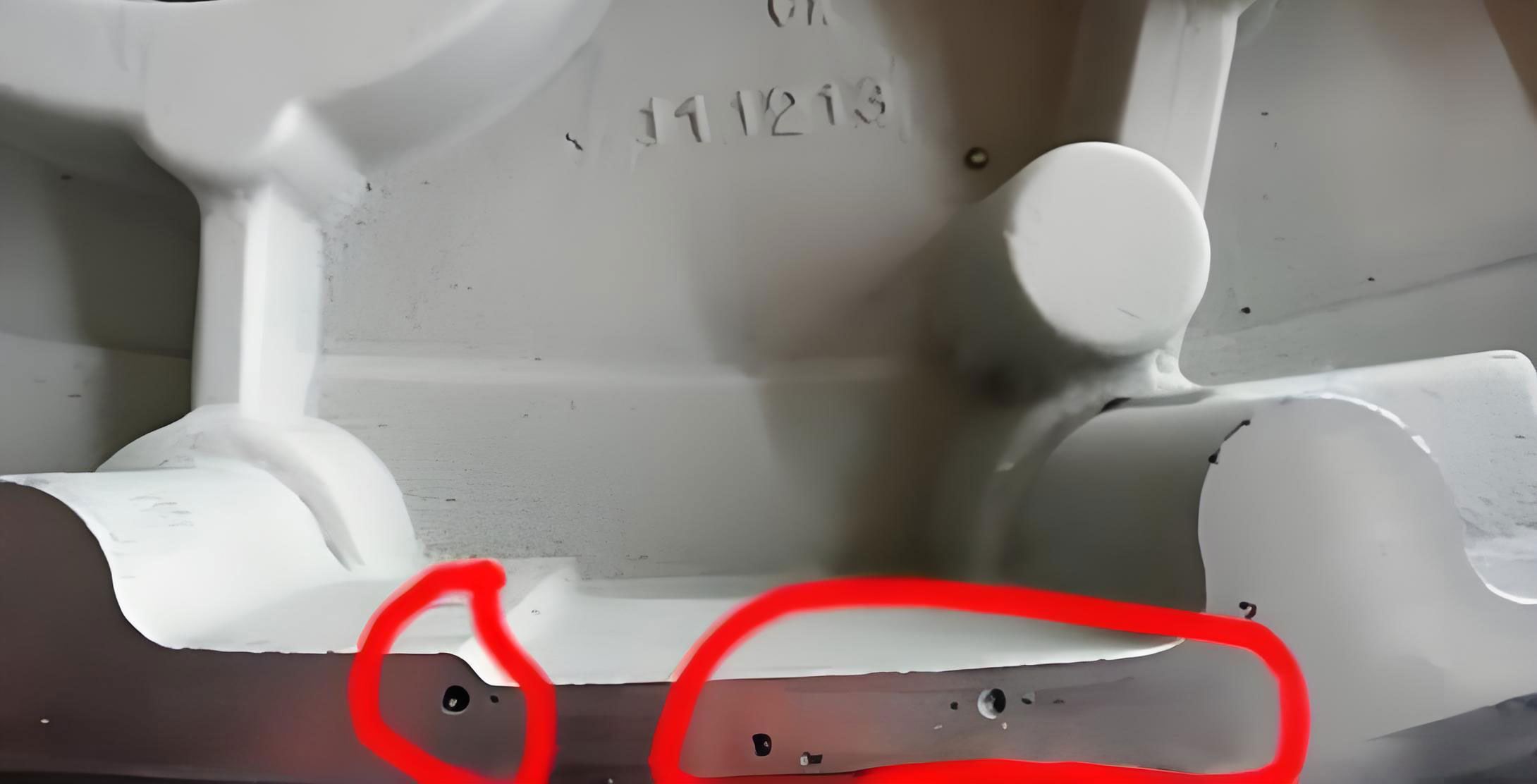
Our journey began with a thorough现状调查 of scrap data spanning eight months. The focus was on two critical compressor components: the支架 (JT170G) and the下轴 (JT170G). The data revealed alarmingly high scrap rates, primarily attributed to various forms of porosity in casting. A visual examination of rejected pieces confirmed the prevalence of both subsurface and surface blowholes, characteristic of gas entrapment during solidification.
To quantify the problem, we compiled statistical data, which is summarized in Table 1. This table clearly illustrates the scrap rate contribution from porosity in casting compared to other defect types.
| Component Code | Total Production Quantity | Total Scrap Pieces | Scrap Rate (%) | Scrap Pieces Due to Porosity in Casting | Contribution of Porosity in Casting to Total Scrap (%) |
|---|---|---|---|---|---|
| JT170G (支架) | 125,000 | 9,750 | 7.8 | 8,300 | 85.1 |
| JT170G (下轴) | 98,000 | 10,290 | 10.5 | 9,150 | 88.9 |
| H80B (底板) | 210,000 | 11,970 | 5.7 | 6,500 | 54.3 |
The data unequivocally showed that porosity in casting was the dominant failure mode, accounting for over 85% of scrap in the critical compressor parts. This justified a focused project to mitigate this specific defect. Visual evidence of the porosity in casting defects was critical for understanding their morphology. Common types observed included spherical subsurface holes and irregular surface pits.
Goal Setting: Establishing a Quantitative Target
Based on the initial data and considering process capabilities, we set a clear, achievable target. Using the Six M’s (Man, Machine, Material, Method, Measurement, Environment) framework for analysis, we concluded that a significant reduction was feasible. The objective was to reduce the scrap rate attributed to porosity in casting for the JT170G支架 and下轴 components from an average of approximately 9.15% to below 4.5% within a defined project timeline. This target represented a more than 50% reduction in defect incidence, which would translate to substantial cost savings and quality improvement.
The rationale for this target was rooted in benchmarking against similar processes and an analysis of controllable factors. We postulated that by addressing key process variables, the incidence of porosity in casting could be dramatically lowered. The target was formally expressed as:
$$ \text{Target Scrap Rate (Porosity)} = S_{target} \leq 4.5\% $$
where the current scrap rate $S_{current}$ was a weighted average of 7.8% and 10.5%, approximately 9.15%.
Root Cause Analysis: Delving into the Origins of Porosity in Casting
A systematic root cause analysis was conducted to identify the factors contributing to porosity in casting. We employed cause-and-effect diagrams and process mapping, focusing on the molten metal treatment, molding sand properties, and core sand contamination. The analysis confirmed several potential causes, which were then validated through experiments and historical data review.
The primary suspected causes for porosity in casting in our process were:
- Low pouring temperature.
- High moisture content in the green sand mold.
- Presence of residual core sand (like coated sand) and bentonite lumps in the return sand system.
- Inadequate gating and venting design (though initially less prominent, it was considered).
- Variations in metal composition and gas content.
Each cause was investigated for its significance. For instance, while molten metal composition was within specification, temperature gradients during pouring were a concern. A detailed breakdown of the contributing factors and their validation status is presented in Table 2.
| Potential Cause | Investigation Method | Data/Observation | Validation as Root Cause | Remarks |
|---|---|---|---|---|
| Low tap temperature | Review of furnace logs and operator records | Temperature consistently measured and recorded above minimum specification (1500°C). | Non-critical | Process discipline was good; tap temperature was not a primary driver. |
| Low pouring temperature | Direct measurement at the pouring cup for sequential molds | Significant drop (up to 30-40°C) observed for the last molds in a batch due to prolonged pouring time and heat loss in ladles. | Critical | Lower temperature increases metal viscosity, reducing gas escape and promoting porosity in casting. |
| High mold sand moisture | Laboratory testing of sand samples from the molding line | Moisture content frequently measured at 4.2-4.8%, exceeding the control limit of 3.0-4.0%. | Critical | Excess moisture vaporizes upon metal contact, generating large volumes of steam that can be trapped, causing porosity in casting. |
| High loss-on-ignition (LOI) and clay content in return sand | Regular sand lab tests | LOI and active bentonite were within specified ranges. | Non-critical | Baseline sand properties were controlled, though contamination was separate. |
| Residual coated sand cores and bentonite lumps | Visual inspection and sieving analysis of return sand | Significant amounts of uncrushed core fragments and clay agglomerates found in the sand system. | Critical | These materials degrade at high temperatures, releasing large amounts of gas directly at the mold-metal interface, leading to severe porosity in casting. |
| Inadequate venting | Design review and simulation | Venting was generally sufficient for the geometry; no major design flaw detected. | Non-critical | Not a primary contributor under current conditions. |
The analysis conclusively identified three critical root causes: low pouring temperature, high mold sand moisture, and contamination from residual cores and clay lumps. Each of these directly influences the gas generation and expulsion dynamics during casting, thereby governing the formation of porosity in casting. The relationship can be conceptually modeled. The total gas pressure $P_{gas}$ contributing to porosity in casting can be considered as a sum of partial pressures from various sources:
$$ P_{gas} = P_{moisture} + P_{core\_decomposition} + P_{metal\_dissolved} $$
Where $P_{moisture}$ is proportional to mold sand moisture content $w$, and $P_{core\_decomposition}$ is a function of contaminant mass $m_c$. The probability of pore formation $Pr_{porosity}$ increases if this pressure exceeds the local metallostatic pressure $P_{metal}$ and the capillary pressure resisting pore nucleation before solidification.
Development and Implementation of Countermeasures
With the root causes established, we devised and implemented specific countermeasures targeting each critical factor. The approach was multifaceted, involving process parameter adjustments, equipment modifications, and enhanced procedural controls.
Countermeasure 1: Stabilizing and Controlling Pouring Temperature
To combat low pouring temperature, we implemented a rigorous temperature management protocol. The target pouring temperature ranges were set based on component geometry and weight: 1400-1370°C for支架 (larger mass) and 1420-1390°C for下轴 (smaller, more intricate). The measures included:
- Continuous Temperature Monitoring: Use of calibrated pyrometers to measure temperature at the pouring cup for every mold, not just the first in a batch.
- Ladle Management: Pre-heating ladles to minimize heat loss and ensuring ladle covers are used to maintain metal temperature during transfer.
- Optimized Pouring Practice: Streamlining the pouring sequence to minimize time between molds. We enforced a “continuous pour” practice where the sprue is kept full to prevent air aspiration, which can also lead to porosity in casting.
- Batch Size Rationalization: Reducing the number of molds poured from a single ladle to ensure the last mold’s temperature remains within the specified window.
The effectiveness of this countermeasure can be modeled by considering heat loss. The temperature drop $\Delta T$ in a ladle can be approximated by:
$$ \Delta T = k \cdot t + \frac{h \cdot A \cdot (T_{metal} – T_{ambient}) \cdot t}{m \cdot C_p} $$
where $k$ is a constant for radiative loss, $t$ is time, $h$ is heat transfer coefficient, $A$ is surface area, $T_{metal}$ and $T_{ambient}$ are temperatures, $m$ is metal mass, and $C_p$ is specific heat. By reducing $t$ (pouring time) and increasing initial $T_{metal}$ (tap temperature slightly), we minimized $\Delta T$, thereby maintaining a higher pouring temperature to reduce viscosity and facilitate gas escape, mitigating porosity in casting.
Countermeasure 2: Precise Control of Green Sand Moisture
High moisture was a major source of steam generation. We tightened control on the molding sand system with two primary actions:
- Increased New Sand Addition Rate: We increased the proportion of new sand in the sand mix from 5% to 8-10%. This dilution helped reduce the average moisture content and lowered the overall gas potential of the sand, directly addressing one source of porosity in casting.
- Enhanced Sand Conditioning and Aeration: Improved mixing and aeration time in the sand mill to ensure more uniform moisture distribution and to allow excess free water to evaporate before use.
- Frequent Moisture Testing: Implemented hourly moisture tests using rapid moisture analyzers at the molding station, with immediate feedback to the sand plant operator for adjustments.
The relationship between moisture content and gas volume is critical. The volume of steam $V_{steam}$ generated per unit volume of sand can be estimated by the ideal gas law applied to the vaporized water:
$$ V_{steam} = \frac{n_{H_2O} R T_{int}}{P} $$
where $n_{H_2O}$ is moles of water = $(\rho_{sand} \cdot w) / M_{H_2O}$, with $\rho_{sand}$ as sand bulk density, $w$ as moisture fraction, $M_{H_2O}$ as molar mass of water, $R$ the gas constant, $T_{int}$ the interface temperature (~1000°C), and $P$ atmospheric pressure. Reducing $w$ from 4.5% to 3.5% significantly reduces $n_{H_2O}$, thereby lowering $V_{steam}$ and the risk of porosity in casting.
Countermeasure 3: Elimination of Sand System Contaminants
Residual core sand and clay lumps were insidious gas generators. Our solution focused on mechanical removal:
- Installation of a Vibrating Screening System: We installed a high-capacity vibrating screen with a mesh size of 2 mm at the discharge point of the return sand hopper. This screen effectively captured uncrushed core fragments, bentonite balls, and other debris before the sand entered the milling and mixing circuit.
- Regular Inspection and Cleaning: Established a routine for inspecting and cleaning the screens to prevent clogging and ensure continuous operation.
- Segregation of Core Knock-out Sand: Where feasible, we directed initial sand from core knockout to a separate processing line for more intensive reclamation before integrating it into the main sand system.
The mass of contaminants $m_c$ entering the system per unit time was drastically reduced. If we assume each contaminant particle generates a gas volume $v_g$ upon decomposition, the total gas volume from this source $V_{cont}$ is:
$$ V_{cont} = N \cdot v_g = \frac{m_c}{\bar{m}_p} \cdot v_g $$
where $N$ is the number of contaminant particles and $\bar{m}_p$ is their average mass. By screening, we reduced $m_c$ to nearly zero, effectively eliminating $V_{cont}$ as a contributor to porosity in casting.
A summary of the implemented countermeasures, their targets, and control parameters is provided in Table 3.
| Root Cause | Countermeasure | Target Parameter / Standard | Monitoring Method | Expected Impact on Porosity in Casting |
|---|---|---|---|---|
| Low Pouring Temperature | Strict temp monitoring, ladle covers, optimized pouring practice | Pouring Temp: 支架: 1400-1370°C; 下轴: 1420-1390°C | Pyrometer reading per mold batch; operator log sheets | Higher fluidity, longer gas escape time, reduced pore formation. |
| High Mold Sand Moisture | Increase new sand addition; improve conditioning; frequent testing | Sand Moisture Content: 3.0 – 4.0% | Hourly moisture tests using rapid analyzer | Reduced steam generation at metal-mold interface. |
| Sand Contamination (Cores, Lumps) | Install vibrating screen at return sand hopper; routine cleaning | Zero visible contaminant particles >2mm in system sand | Visual inspection of screened waste; sand sieve analysis weekly | Elimination of localized high-gas-generation sites. |
Results, Validation, and Discussion
The countermeasures were implemented over a three-month period, with careful monitoring of key parameters and scrap rates. Post-implementation data was collected for an additional four months to ensure stability and validate the results. The outcome was a dramatic reduction in the scrap rate due to porosity in casting.
The post-implementation scrap data is summarized in Table 4, comparing it with the baseline data.
| Component Code | Baseline Scrap Rate from Porosity (%) (Jan-Aug 2018) | Post-Implementation Scrap Rate from Porosity (%) (Months 4-7 after project start) | Absolute Reduction (%) | Reduction Relative to Baseline (%) |
|---|---|---|---|---|
| JT170G (支架) | 7.8 (overall, ~85.1% of which is porosity) | 3.2 | 4.6 | ~59.0% |
| JT170G (下轴) | 10.5 (overall, ~88.9% of which is porosity) | 4.1 | 6.4 | ~60.9% |
For a consolidated view, the average scrap rate from porosity in casting for these two critical components dropped from approximately 9.15% to 3.65%, comfortably achieving and exceeding our target of 4.5%. This represents a 60% reduction in defects attributed to porosity in casting. The overall scrap rate for the components also saw a corresponding decline, improving overall plant efficiency.
The success can be attributed to the systemic approach addressing multiple facets of gas generation. The relationship between the controlled variables and the scrap rate can be expressed through a simplified empirical model. If we denote the scrap rate $S$ as a function of pouring temperature $T_p$, sand moisture $w$, and contaminant level $C$, a multi-variable regression on our process data suggested a relationship like:
$$ S = \alpha_0 – \alpha_1 T_p – \alpha_2 w – \alpha_3 C + \epsilon $$
where $\alpha_i$ are positive coefficients, and $\epsilon$ encompasses other noise factors. Our interventions increased $T_p$ (by minimizing drop), decreased $w$, and reduced $C$ to near zero, all contributing to a lower $S$, i.e., reduced porosity in casting.
Furthermore, the control of porosity in casting had secondary benefits. Mechanical testing of castings showed improved tensile strength and fatigue life, as pores act as stress raisers. The reduction in porosity in casting also enhanced pressure tightness, a critical requirement for compressor components. We estimated the annual cost savings from reduced scrap and rework to be significant, validating the investment in process improvements.
Conclusion and Future Perspectives
In conclusion, this project demonstrated that a systematic, data-driven approach is highly effective in combating porosity in casting. By identifying low pouring temperature, high mold sand moisture, and sand contamination as the critical root causes, and implementing targeted countermeasures involving temperature management, sand property control, and mechanical screening, we successfully reduced the scrap rate due to porosity in casting by over 60%, achieving a rate well below the 4.5% target. The key to success was treating the foundry process as an integrated system where metal, mold, and method interact.
The battle against porosity in casting is ongoing. Future work will focus on implementing real-time process monitoring and advanced simulation tools to predict gas entrapment. For instance, computational fluid dynamics (CFD) simulations of mold filling and solidification can identify potential hotspots for porosity in casting before tooling is finalized. Additionally, exploring the use of advanced sand additives that reduce gas generation or improve permeability could provide another avenue for defect reduction. Continuous improvement in sand reclamation efficiency will also help maintain low contaminant levels.
Ultimately, controlling porosity in casting requires constant vigilance, disciplined process execution, and a willingness to invest in process understanding and technology. The lessons learned from this project on air conditioning compressor castings are universally applicable to other ferrous and non-ferrous casting operations where gas defects pose a challenge. By sharing these insights, I hope to contribute to the broader foundry industry’s efforts to produce higher integrity castings with minimal defects, ensuring reliability and performance in final products.