
In the field of automotive manufacturing, the connecting rod is a critical component that links the piston to the crankshaft, enduring complex forces such as gas pressure, impact loads, bending stresses, and dynamic loads during operation. Therefore, it must exhibit high fatigue resistance, toughness, and plasticity. Traditional machining methods for connecting rods involve processes like broaching, grinding, boring, and drilling, which are characterized by long production cycles and high costs. In contrast, the cracking technology for connecting rods offers advantages in precision, quality, and efficiency, gradually replacing conventional methods. However, cracking processes impose strict material requirements, often leading to issues like incomplete cracking or deformation of the big end hole. To address these challenges, I have embarked on a comprehensive study of the lost wax casting process for dual-metal connecting rods. This investigation aims to achieve metallurgical bonding between two distinct metals, facilitating the cracking process and enhancing the overall quality of the rods. Lost wax casting, also known as investment casting, is a precision casting technique ideal for producing complex geometries with excellent surface finish and dimensional accuracy. In this article, I will detail the entire process, from design and simulation to optimization and experimental validation, emphasizing the pivotal role of lost wax casting in advancing connecting rod manufacturing.
The connecting rod under investigation consists of a main body made of low-carbon steel, specifically analogous to AISI 1026, and a cracking material made of T10A steel. The design requires uniform wall thickness, good surface quality, and freedom from internal defects such as shrinkage porosity and cavities. The three-dimensional model of the connecting rod is conceptualized to optimize the casting process. To ensure effective feeding and minimize defects, a side-pouring gating system is designed. This system includes a sprue, runners, and three ingates, all with rounded edges to enhance heat dissipation and reduce stress concentrations. The gating system is meticulously planned to facilitate smooth metal flow and directional solidification, which are crucial aspects of lost wax casting. The following table summarizes the key design parameters for the casting setup:
| Component | Material | Dimensions/Notes |
|---|---|---|
| Connecting Rod Body | Low-Carbon Steel (AISI 1026 equivalent) | Uniform wall thickness, optimized for cracking |
| Cracking Material | T10A Steel | Plate form, 2 mm thickness, inserted during casting |
| Gating System | Wax pattern material | Side-pouring design with 3 ingates, rounded edges |
| Shell Mold | Zircon sand face coat, silica sol binder | 5 layers applied, dried and baked |
The lost wax casting process begins with the creation of a wax pattern. In this study, I use medium-temperature wax to form the patterns of the connecting rods. Four wax patterns are assembled onto a gating system using rectangular ingates, ensuring proper alignment and stability. This wax assembly is then subjected to shell building, where a ceramic shell is formed by alternating dips in a slurry of silica sol and zircon flour, followed by stuccoing with zircon sand. After applying five layers, the shell is sealed and dried. This shell mold is essential in lost wax casting, as it provides the precise cavity for metal pouring. The integrity of the shell directly impacts the final casting quality, making it a critical step in the lost wax casting methodology.
To analyze the casting process and predict potential defects, I employ numerical simulation using ProCAST software. This advanced tool allows for the simulation of filling, solidification, and stress distribution, which are integral to optimizing the lost wax casting process. The initial conditions are set based on material properties and process parameters. The main body material has a liquidus temperature of 1,516°C and a solidus temperature of 1,430°C. The pouring temperature is set at 1,600°C, the cracking material preheat temperature at 400°C, and the shell preheat temperature at 1,150°C. Cooling occurs under ambient conditions, with a filling time of 3 seconds, corresponding to a pouring velocity of 48.62 mm/s as calculated by the software’s velocity calculator. The simulation domain includes the entire casting assembly, and the governing equations for fluid flow and heat transfer are solved numerically. For instance, the heat conduction during solidification can be described by the Fourier equation: $$ \frac{\partial T}{\partial t} = \alpha \nabla^2 T $$ where \( T \) is temperature, \( t \) is time, and \( \alpha \) is thermal diffusivity. This equation underpins the simulation of thermal gradients in lost wax casting.
The filling process simulation reveals a smooth and progressive metal flow. At 24.4% filling, the liquid metal first fills the bottom of the shell mold, then gradually ascends to fill the rod body and big end. By 81.2% filling, the lower portion around the cracking material is filled, while the upper part remains incomplete. Since the metal temperature remains above the liquidus, this does not hinder the bonding between the main body and cracking material. The sequential filling minimizes turbulence and oxide formation, which is a key benefit of lost wax casting. The solidification simulation shows that solidification initiates at the cracking material location at 10.9 seconds, with a solid fraction of 77%, while other areas remain liquid. This early solidification ensures tight bonding at the interface. By 36.1 seconds, solidification propagates outward from the casting surface inward, promoting directional solidification. At 231.2 seconds, the casting solid fraction reaches 86.7%, but the sprue remains at 40% solid, acting as an effective feeder to compensate for shrinkage—a hallmark of well-designed lost wax casting systems. Complete solidification occurs at 506.1 seconds. The defect analysis indicates that shrinkage porosity and cavities are confined to the pouring cup and sprue, with no defects in the casting itself. Stress distribution shows a maximum effective stress of 444.5 MPa at the ingates, which may lead to cold cracks, but since the ingates are removed during post-processing, this does not affect the final part quality. The simulation confirms the feasibility of the side-pouring gating system in lost wax casting for dual-metal rods.
To optimize the lost wax casting process parameters, I conduct an orthogonal experiment focusing on three key factors: pouring temperature, cracking material preheat temperature, and shell preheat temperature. Each factor is tested at three levels, and the responses measured are shrinkage porosity percentage and maximum effective stress. The orthogonal array L9 (3^3) is used, and the results are summarized in the table below. The analysis of range (R) indicates the influence order of factors on defects and stress. For shrinkage porosity, the order is shell preheat temperature > pouring temperature > cracking material preheat temperature. For effective stress, the order is similar, emphasizing the critical role of shell temperature in lost wax casting. The optimal parameters are determined as pouring temperature of 1,600°C, shell preheat temperature of 1,200°C, and cracking material preheat temperature of 500°C. Under these conditions, simulation shows minimal defects only in the gating system and reduced stress in the casting body. This optimization highlights the importance of precise thermal management in lost wax casting to achieve high-quality dual-metal components.
| Experiment No. | Pouring Temperature (°C) | Cracking Material Preheat (°C) | Shell Preheat (°C) | Shrinkage Porosity (%) | Effective Stress (MPa) |
|---|---|---|---|---|---|
| 1 | 1,580 | 400 | 1,100 | 68.1 | 441.2 |
| 2 | 1,580 | 500 | 1,150 | 69.4 | 422.3 |
| 3 | 1,580 | 600 | 1,200 | 67.3 | 424.6 |
| 4 | 1,600 | 400 | 1,150 | 69.0 | 444.4 |
| 5 | 1,600 | 500 | 1,200 | 67.4 | 373.9 |
| 6 | 1,600 | 600 | 1,100 | 68.2 | 398.1 |
| 7 | 1,620 | 400 | 1,200 | 67.0 | 392.0 |
| 8 | 1,620 | 500 | 1,100 | 67.6 | 439.6 |
| 9 | 1,620 | 600 | 1,150 | 68.1 | 416.1 |
The mathematical model for optimizing the lost wax casting process can be expressed using a response surface methodology. For instance, the shrinkage porosity (SP) as a function of the factors can be approximated by a quadratic equation: $$ SP = \beta_0 + \beta_1 T_p + \beta_2 T_c + \beta_3 T_s + \beta_4 T_p T_c + \beta_5 T_p T_s + \beta_6 T_c T_s + \beta_7 T_p^2 + \beta_8 T_c^2 + \beta_9 T_s^2 $$ where \( T_p \) is pouring temperature, \( T_c \) is cracking material preheat temperature, \( T_s \) is shell preheat temperature, and \( \beta_i \) are coefficients determined from experimental data. This model aids in predicting outcomes for various parameter combinations in lost wax casting.
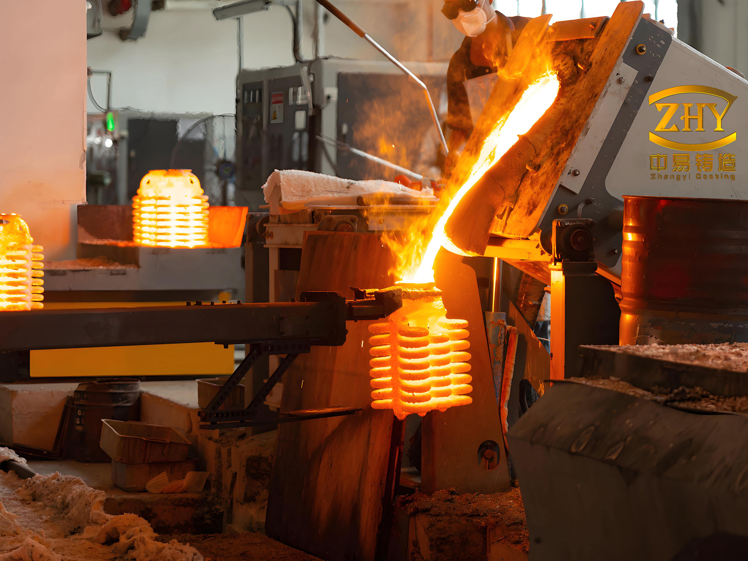
Following the simulation and optimization, I proceed to practical trials to validate the lost wax casting process. The main body material is melted in a medium-frequency induction furnace, with the composition verified using a spectrometer to ensure it matches the AISI 1026 equivalent. The cracking material, T10A steel plates, is prepared with dimensions of 2 mm thickness. Initially, I attempt a trial where the shell mold and cracking material are co-baked in a furnace. However, this results in severe oxidation and partial melting of the T10A due to prolonged high-temperature exposure, leading to poor bonding and surface defects such as shrinkage porosity and cold shuts. This setback underscores the sensitivity of lost wax casting to thermal history and oxidation control.
To overcome these issues, I modify the lost wax casting procedure. The shell mold is baked separately at 1,200°C. Meanwhile, the cracking material is preheated to 500°C just before insertion. After baking, the preheated cracking material is quickly inserted into the shell mold through预留 spaces left during shell making, and the ends are sealed with refractory clay. This step is performed within a short time frame to minimize oxidation. Then, at a shell temperature of 1,200°C, the molten steel is poured at 1,600°C. The rapid insertion and pouring reduce exposure to oxygen, preserving the integrity of both materials. This refined approach is a testament to the adaptability of lost wax casting in handling dual-metal configurations.
The resulting castings exhibit excellent surface quality without cracks, shrinkage, or porosity. The interface between the low-carbon steel and T10A shows a wavy, metallurgically bonded structure, indicating interdiffusion of carbon and strong adhesion. Microhardness measurements across the interface reveal a gradual transition, with hardness values intermediate between the two metals, confirming effective bonding. The success of this trial validates the optimized lost wax casting parameters and the modified insertion technique. The table below summarizes the key outcomes from the experimental validation:
| Aspect | Observation | Implication for Lost Wax Casting |
|---|---|---|
| Surface Quality | No visible defects on casting body | Lost wax casting produces high-integrity surfaces |
| Interface Bonding | Metallurgical bonding with carbon diffusion | Lost wax casting enables strong dual-metal joints |
| Hardness Profile | Gradual transition across interface | Lost wax casting minimizes stress concentrations |
| Defect Location | Shrinkage only in gating system | Lost wax casting allows defect control via design |
The thermal dynamics during lost wax casting can be further analyzed using the Chvorinov’s rule for solidification time: $$ t_s = B \left( \frac{V}{A} \right)^n $$ where \( t_s \) is solidification time, \( V \) is volume, \( A \) is surface area, \( B \) is a mold constant, and \( n \) is an exponent typically around 2. In this study, the design ensures that the gating system has a higher \( V/A \) ratio, acting as a feeder to prolong solidification and feed the casting, which is a strategic advantage in lost wax casting.
In conclusion, my investigation into the lost wax casting process for dual-metal cracking connecting rods demonstrates significant advancements in manufacturing efficiency and product quality. Through meticulous design of a side-pouring gating system, comprehensive numerical simulation, and systematic optimization via orthogonal experiments, I have identified optimal parameters: pouring temperature of 1,600°C, shell preheat temperature of 1,200°C, and cracking material preheat temperature of 500°C. The modified process, involving separate baking of the shell and rapid insertion of preheated cracking material, successfully produces castings with metallurgical bonding and minimal defects. This work underscores the versatility and precision of lost wax casting in producing complex dual-metal components for automotive applications. Future research could explore other material combinations or scale up the process for industrial production, further leveraging the capabilities of lost wax casting. The integration of simulation tools like ProCAST continues to enhance the predictability and optimization of lost wax casting, making it a cornerstone of modern precision manufacturing.
Throughout this study, the term lost wax casting has been emphasized repeatedly, reflecting its central role in achieving the desired outcomes. The process not only facilitates the creation of intricate shapes but also enables the integration of dissimilar metals, opening new avenues for component design. As automotive engines evolve towards higher performance and efficiency, techniques like lost wax casting will remain indispensable. I envision further innovations in lost wax casting, such as the use of advanced ceramics for shells or real-time monitoring systems, to push the boundaries of what is possible in metal casting. The journey from wax pattern to final casting exemplifies the artistry and science embedded in lost wax casting, a tradition that continues to evolve with technology.